
Device and method for accurately and visually testing soil displacement in seismic piping destroy

A technology of piping damage and soil displacement, applied in the field of accurate visualization test device for soil displacement during earthquake piping damage, can solve the problems of discontinuous, invisible and soil deformation in displacement field measurement, and solve the internal deformation and deformation of soil Discontinuous and invisible displacement field measurement, simple test model, and strong operability

Active Publication Date: 2018-06-15
HOHAI UNIV
View PDF6 Cites 15 Cited by
  • Summary
  • Abstract
  • Description
  • Claims
  • Application Information

AI Technical Summary

Problems solved by technology

[0005] The purpose of the present invention is to overcome the above-mentioned deficiencies and defects, and propose a test device and test method for accurate visualization of soil displacement during earthquake piping damage, which solves the problems of soil internal deformation and displacement field measurement when soil piping damage occurs under earthquakes Discontinuity and invisible problems, thus realizing the purpose of accurate visualization model test of piping failure process under earthquake

Method used


Image

  • Device and method for accurately and visually testing soil displacement in seismic piping destroy

Examples


Embodiment Construction

[0037] The technical solutions of the present invention will be clearly and completely described below in conjunction with specific embodiments and the accompanying drawings in the examples of the present invention.

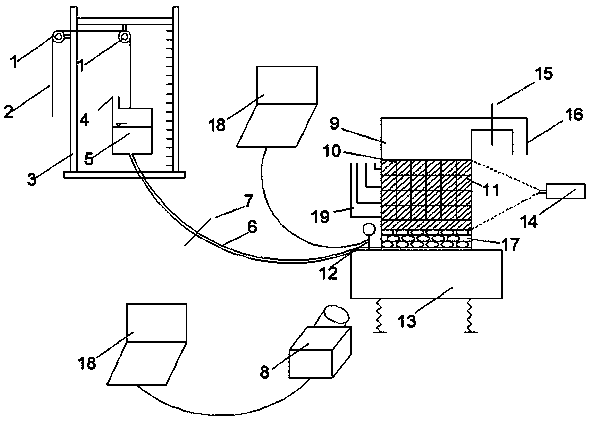
[0038] Such as figure 1 As shown, the present invention is a test device for accurate visualization of soil displacement when earthquake piping is damaged, including:

[0039] A water supply device 5, the top of the water supply device 5 is provided with a water inlet 4, the bottom of the water supply device 5 is provided with a water inlet pipe 6, and the water inlet pipe 6 is provided with a water inlet valve 7 and a flow meter 12;

[0040] A transparent model box 9, the height of the transparent model box 9 is lower than the height of the water supply device 5, and the bottom of the transparent model box 9 is provided with an interface that communicates with the water inlet pipe 6 on the water supply device 5; the transparent model box 9 A plurality of pore p...


PUM


Abstract

The invention discloses a device and method for accurately and visually testing soil displacement in seismic piping destroy. The device comprises a water supply device and a transparent model box. Thetransparent model box is lower than the water supply device. The bottom of the transparent model box is provided with an interface communicated with the water supply device. A plurality of pore pressure measuring devices are equidistantly disposed in the transparent model box. The device also comprises a shaking platform for storing the transparent model box, a water head adjustment mechanism foradjusting water head height of the water supply device, and a digital observing system. Through combination of saturated transparent soil samples and a particle image processing technology, the problem that the soil internal deformation and displacement field cannot be continuously measured and are invisible in soil piping destroy under action of earthquake is solved so that the piping destroy process visualization is realized under action of earthquake.

Description

technical field [0001] The invention relates to the technical field of geotechnical engineering visualization tests, in particular to an accurate visualization test device and test method for soil displacement when earthquake piping damages. Background technique [0002] Geotechnical engineering is a branch of civil engineering. It is a discipline involving soil mechanics, rock mechanics, engineering geology, etc. to solve engineering technical problems related to rock and soil in various practical projects, and is closely connected with people's lives. Earthquake refers to the vibration caused by the rapid release of energy from the earth's crust, and a natural phenomenon in which seismic waves are generated during the vibration process. Earthquakes can cause the collapse of various buildings and structures, damage to equipment and facilities, and interruption of transportation and communication. Direct disasters such as landslides, debris flows, piping and other secondary ...

Claims


Application Information

Patent Timeline
Patent Type & Authority Applications(China)
IPC IPC(8): G01N33/24
CPCG01N33/24
Inventor 倪小东徐硕王媛左翔宇曾乾坤
Owner HOHAI UNIV
Learn More