Bidirectional optical amplifier applied to extra-long-distance high-precision time transmission

An optical amplifier and amplifier technology, applied in the directions of light guides, optics, instruments, etc., can solve problems such as the inability to meet the needs of high-precision time-frequency transmission, achieve high gain, and overcome the effect of transmission bottlenecks

Inactive Publication Date: 2018-06-15
INST OF SEMICONDUCTORS - CHINESE ACAD OF SCI
View PDF7 Cites 2 Cited by
  • Summary
  • Abstract
  • Description
  • Claims
  • Application Information

AI Technical Summary

Problems solved by technology

In order to ensure that the noise introduced by the round-trip signal light is the same, the signal light needs to be transmitted back and forth in the same optical fiber. The traditional one-way EDFA cannot meet the high-precision time-frequency transmission requirements.

Method used


Image

  • Bidirectional optical amplifier applied to extra-long-distance high-precision time transmission

Examples


Embodiment Construction

[0020] In order to make the purpose, technical solutions and advantages of the present disclosure clearer, the present disclosure will be further described in detail below in conjunction with specific embodiments and with reference to the accompanying drawings. It should be noted that, in the drawings or descriptions of the specification, similar or identical parts all use the same figure numbers. Implementations not shown or described in the accompanying drawings are well known to those of ordinary skill in the art. Additionally, while illustrations of parameters including particular values ​​may be provided herein, it should be understood that the parameters need not be exactly equal to the corresponding values, but rather may approximate the corresponding values ​​within acceptable error margins or design constraints.

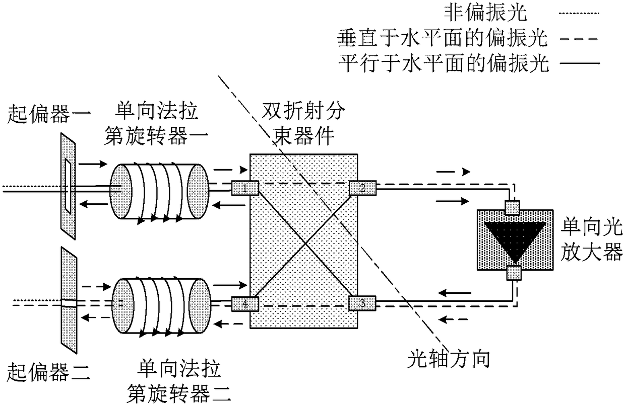
[0021] The bidirectional optical amplifier proposed by the embodiments of the present disclosure is mainly used in ultra-long-distance high-precision time t...


PUM


Abstract

The invention discloses a bidirectional optical amplifier applied to an extra-long-distance high-precision time transmission system. The bidirectional optical amplifier comprises a first polarizer, asecond polarizer, a first unidirectional Faraday rotator, a second unidirectional Faraday rotator, a birefringence beam splitter and a unidirectional optical amplifier. The first polarizer, the firstunidirectional Faraday rotator, the port 1 and the port 2 of the birefringence beam splitter, the unidirectional optical amplifier, the port 3 and the port 4 of the birefringence beam splitter, the second unidirectional Faraday rotator and the second polarizer form a first amplification optical path. The second polarizer, the second unidirectional Faraday rotator, the port 4 and the port 2 of thebirefringence beam splitter, the unidirectional optical amplifier, the port 3 and the port 1 of the birefringence beam splitter, the first unidirectional Faraday rotator and the first polarizer form asecond amplification optical path.

Description

technical field [0001] The disclosure relates to the field of time transfer and synchronization, in particular to a bidirectional optical amplifier applied to ultra-long-distance high-precision time transfer. Background technique [0002] Accurate time transfer and synchronization is one of the common basic issues and key technologies in cutting-edge scientific research and major infrastructure such as national / international time-frequency systems, global navigation and positioning, geodesy and observation, precision metrology, and deep space exploration. With the development of new time-frequency references, methods such as microwave transmission based on satellite links cannot meet the long-distance transmission of such high-precision frequencies due to the limitation of transmission accuracy. Therefore, it is urgent to research and develop new ultra-long-distance high-precision time transfer methods and technologies. At present, the accuracy of transmission using optical...

Claims


Application Information

Patent Timeline
Patent Type & Authority Applications(China)
IPC IPC(8): G02B6/27
CPCG02B6/27G02B6/274
Inventor 陈伟黄庆超穆春元刘建国祝宁华
Owner INST OF SEMICONDUCTORS - CHINESE ACAD OF SCI
Why Eureka
Try Eureka