Vacuum packaging cover plate and vacuum packaging device
A technology of vacuum encapsulation and cover plate, which is applied in the direction of electrical components, incandescent lamp parts, shells/tube shells of illuminants, etc., which can solve the problem of reducing the area of the getter coating and failing to improve the utilization of the getter coating area. rate, large proportion of coating layer, etc.
- Summary
- Abstract
- Description
- Claims
- Application Information
AI Technical Summary
Problems solved by technology
Method used
Image

Examples
Embodiment Construction
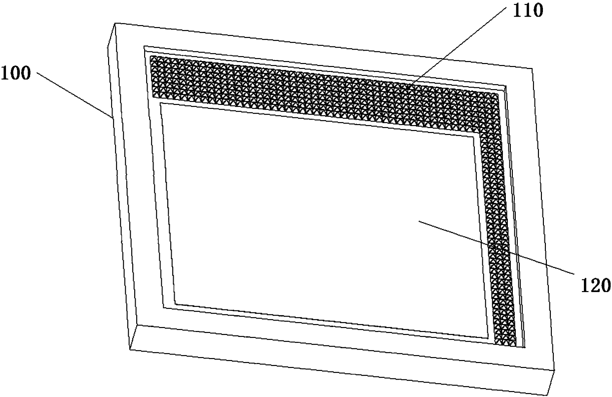
[0018] The core of the present application is to provide a vacuum packaging cover plate which can improve the area utilization ratio of the getter coating.
[0019] In order to make the purposes, technical solutions and advantages of the embodiments of the present application clearer, the technical solutions in the embodiments of the present application will be clearly and completely described below in conjunction with the drawings in the embodiments of the present application. Obviously, the described embodiments It is a part of the embodiments of this application, not all of them. Based on the embodiments in this application, all other embodiments obtained by persons of ordinary skill in the art without making creative efforts belong to the scope of protection of this application.
[0020] see below figure 1 , figure 1 It is a schematic structural diagram of a vacuum packaging cover plate provided by the embodiment of the present application.
[0021] The vacuum-encapsula...
PUM
 Abstract
Description
Claims
Application Information
PatSnap Eureka turns technology decisions into work you can execute. Powered by our Innovation Knowledge Graph, it runs expert workflows across engineering, life sciences, materials and intellectual property. Get your review-ready output in minutes.


