Integrated one-machine-multi-gun charging pile system and implementation method thereof
A technology of a charging pile system and a realization method, applied in the field of circuit devices or systems, can solve the problem that charging power cannot be flexibly dispatched, achieve good economic and social benefits, and improve the use efficiency.
- Summary
- Abstract
- Description
- Claims
- Application Information
AI Technical Summary
Problems solved by technology
Method used
Image
Examples
no. 1 example
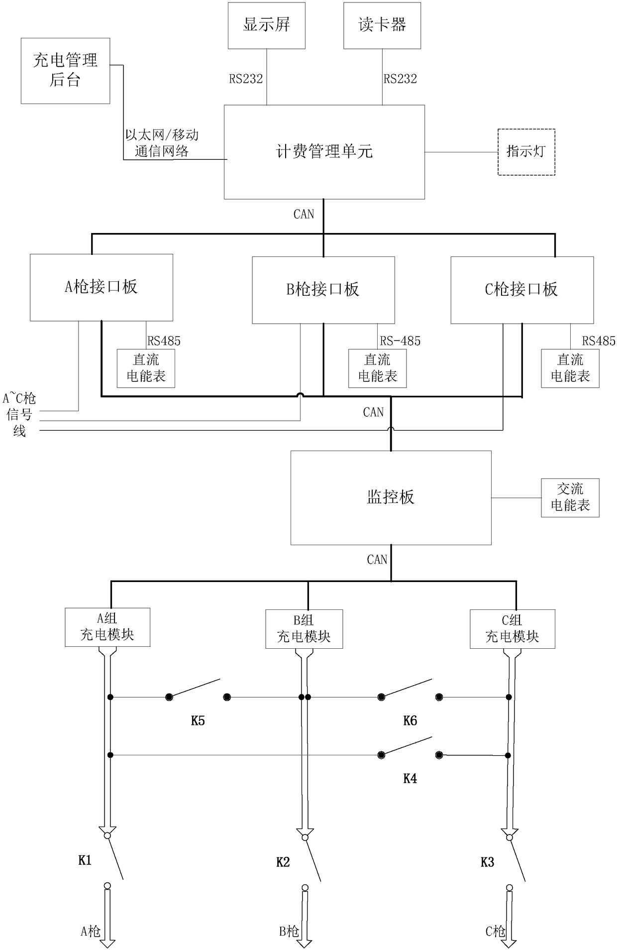
[0041] A typical one machine four gun charging pile system, the system is only equipped with three charging guns, each charging gun is equipped with a gun line that can pass through 250A (maximum current), and the extra hole corresponding to the gun line can be directly used as an outlet Plug it up. Such as figure 1 As shown, the charging pile system includes three charging guns (A gun, B gun and C gun) and three groups of charging modules (A group charging module, B group charging module and C group charging module), six control switches K1 ~ K6 They are respectively connected between each group of charging modules and charging guns, and the required number of charging modules are dispatched to each charging gun by selecting the on-off of each control switch. Among them, the control switch K1 is connected between the charging module of the group A and the gun A, when the control switch K1 is closed, the charging module of the group A is connected to the gun A; the control sw...
no. 2 example
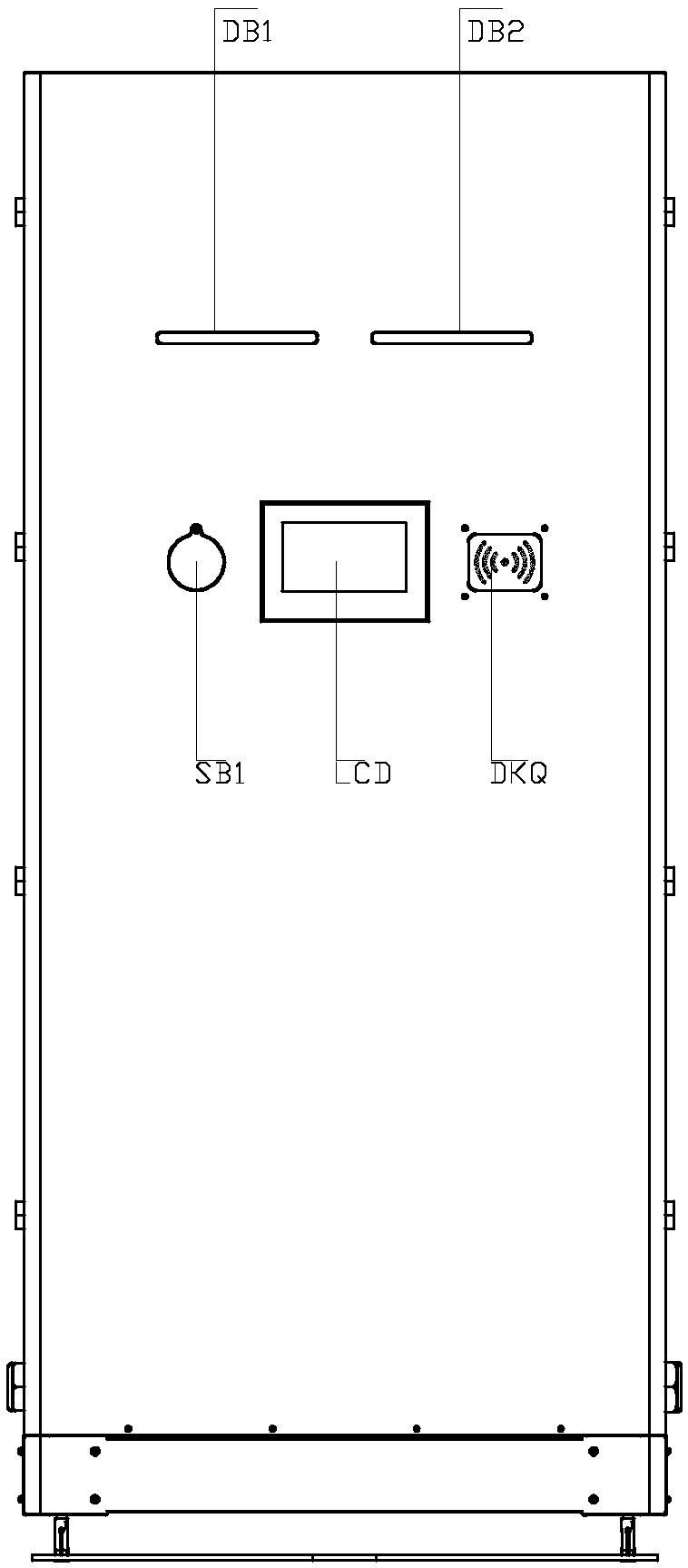
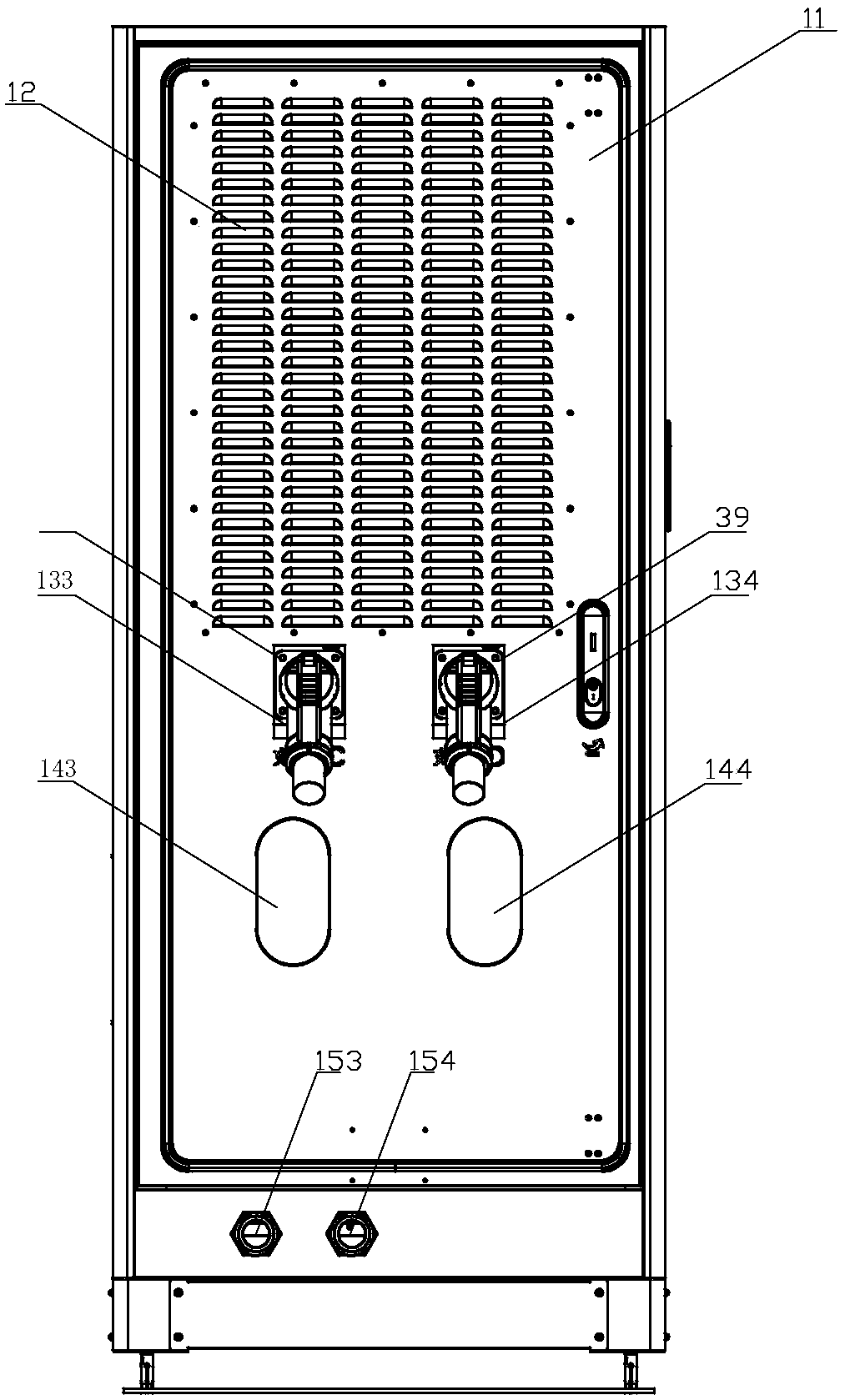
[0046] A typical embodiment of a charging pile system with four guns in one machine, the system is equipped with four charging guns. Such as Figure 2a , 2b As shown in , 2c, the charging pile includes a cabinet that can be opened left and right. There is an operation display screen on the upper part of the front of the cabinet, and two indicator lights (light bars) DB1 / DB2 are arranged on the top of the display screen. Each light bar The corresponding states of the two charging guns are displayed in red, green, and yellow with synchronous flashing, horse racing flashing, and constant light. There is an emergency stop button SB1 on the left side of the display, and there is an anti-stop button just above the emergency stop button SB1. Protective cover for accidental touch, a card reader DKQ is installed on the right side of the display screen, the surface of the card swiping area of the card reader DKQ is made of acrylic board, and a non-contact card reader circuit is insta...
PUM
 Abstract
Description
Claims
Application Information
 - R&D
- Intellectual Property
- Life Sciences
- Materials
- Tech Scout
- Unparalleled Data Quality
- Higher Quality Content
- 60% Fewer Hallucinations
Browse by: Latest US Patents, China's latest patents, Technical Efficacy Thesaurus, Application Domain, Technology Topic, Popular Technical Reports.
© 2025 PatSnap. All rights reserved.Legal|Privacy policy|Modern Slavery Act Transparency Statement|Sitemap|About US| Contact US: help@patsnap.com


