
Cloth shearing device for textile manufacturing

A technology for textiles and cloth cutting, which is applied in the field of cloth cutting devices for textile production, can solve problems such as affecting the quality of cloth, existing hidden dangers, and reducing cutting efficiency, and achieves the effect of eliminating hidden dangers, improving efficiency, and improving quality and efficiency.

Inactive Publication Date: 2018-06-19
江苏爱纺纺织有限公司
View PDF0 Cites 4 Cited by
  • Summary
  • Abstract
  • Description
  • Claims
  • Application Information

AI Technical Summary

Problems solved by technology

[0003] When the fabric is formed by weaving, it needs to be cut to facilitate the packaging and processing of the fabric. However, most of the existing cutting devices have a simple structure. When cutting, the cutting knife can easily drive the fabric, resulting in uneven cutting and burr edges. It affects the quality of the fabric. At the same time, when the existing cutting device cuts the fabric, it needs to manually pull the follow-up fabric to the other side of the cutting knife, which not only has potential safety hazards, but also reduces the efficiency of cutting. Therefore, we have designed a Cloth cutting device for textile production to solve the above problems

Method used


Image

  • Cloth shearing device for textile manufacturing
  • Cloth shearing device for textile manufacturing

Examples


Embodiment Construction

[0014] The following will clearly and completely describe the technical solutions in the embodiments of the present invention with reference to the accompanying drawings in the embodiments of the present invention. Obviously, the described embodiments are only some, not all, embodiments of the present invention.

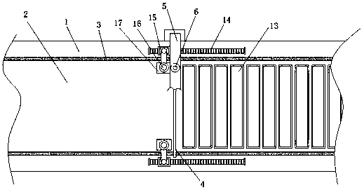
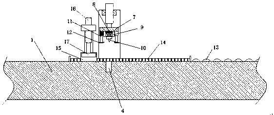
[0015] refer to Figure 1-2 , a cloth cutting device for textile production, comprising a cutting platform 1, the middle part of the cutting platform 1 is provided with a cutting area 2 along its length direction, both sides of the cutting area 2 are provided with a limiting plate 3 along its length direction, and the cutting area 2 The middle part of the cutting groove 4 is provided with a cutting groove 4 along its width direction, and a support beam 5 arranged along the width direction of the cutting platform 1 is installed directly above the cutting groove 4, and two first lifting cylinders 6 are installed through the support beam 5, and The piston rods of the tw...


PUM


Abstract

The invention discloses a cloth shearing device for textile manufacturing. The cloth shearing device for textile manufacturing comprises a shearing platform; a shearing region is arranged at the middle part of the shearing platform in a length direction; limiting plates are arranged on the two sides of the shearing region in the length direction respectively; a shearing groove is arranged at the middle part of the shearing region in a width direction; a supporting beam which is installed in the width direction of the shearing platform among the shearing groove passes through the upper side ofthe shearing groove and is provided with two first lifting cylinders in a penetrating manner; piston rods of the two first lifting cylinders are arranged facing the shearing groove; and a mounting plate is fixedly installed between the piston rods of the two first lifting cylinders. The cloth shearing device provided by the invention is novel in design and convenient and rapid to use, can ensure the shearing smoothness, improves the quality of cloth, can automatically convey the cloth end to the other side of a shearing cutter for convenience in subsequent shearing without manual pulling, eliminates safety hidden dangers and improves the shearing efficiency.

Description

technical field [0001] The invention relates to the technical field of textiles, in particular to a cloth cutting device for textile production. Background technique [0002] The original meaning of textile is taken from the general term of spinning and weaving, but with the continuous development and improvement of the textile knowledge system and subject system, especially after the emergence of non-woven textile materials and three-dimensional composite weaving technologies, the current textile is not only a traditional Hand spinning and weaving also include garment, industrial and decorative textiles produced by non-woven technology, modern three-dimensional weaving technology, and modern electrostatic nano-netting technology. Therefore, modern textile refers to a multi-scale structure processing technology of fibers or fiber aggregates. Ancient Chinese textile and printing and dyeing technology has a very long history. As early as the primitive society, the ancients kn...

Claims


Application Information

Patent Timeline
IPC IPC(8): D06H7/00
CPCD06H7/00
Inventor 薛翔议薛枫泉
Owner 江苏爱纺纺织有限公司
Learn More