Antenna transmission device

A transmission device and antenna technology, which is applied to the transmission device, gear transmission device, antenna and other directions, can solve the problems of difficult installation, increased cost, and large layout space, and achieves the effects of simple control, convenient replacement and high integration.

Pending Publication Date: 2018-06-19
PROSE TECH CO LTD
View PDF15 Cites 5 Cited by
  • Summary
  • Abstract
  • Description
  • Claims
  • Application Information

AI Technical Summary

Problems solved by technology

When it is necessary to set up a multi-frequency antenna, the transmission mode of the multi-frequency antenna is a simple superposition of a single-frequency antenna, that is, one motor alone controls one phase shifter. For a multi-frequency antenna, it is necessary to realize the separate adjustment of multiple phase shifters It is necessary to configure multiple motors. Due to the high price and heavy weight of the motor, it not only leads to a large antenna size, but also increases the cost. There are disadvantages such as complex structure, difficult production, and high cost.
[0004] With the rapid development of base station antenna technology, some manufacturers at home and abroad have proposed a transmission mechanism that controls the downtilt angle of the antenna through two drives or even one drive, mainly through the revolution and self-propagation of the gear to drive multiple antennas with fewer drive devices Array shifting method, this scheme with less belts and more saves the number of motors, but the existing scheme is complex in structure, difficult to install, and the layout takes up a lot of space, and the volume of the antenna is still large

Method used


Image

  • Antenna transmission device
  • Antenna transmission device
  • Antenna transmission device

Examples


Embodiment Construction

[0032] The technical solutions of the embodiments of the present invention will be clearly and completely described below in conjunction with the accompanying drawings of the present invention.

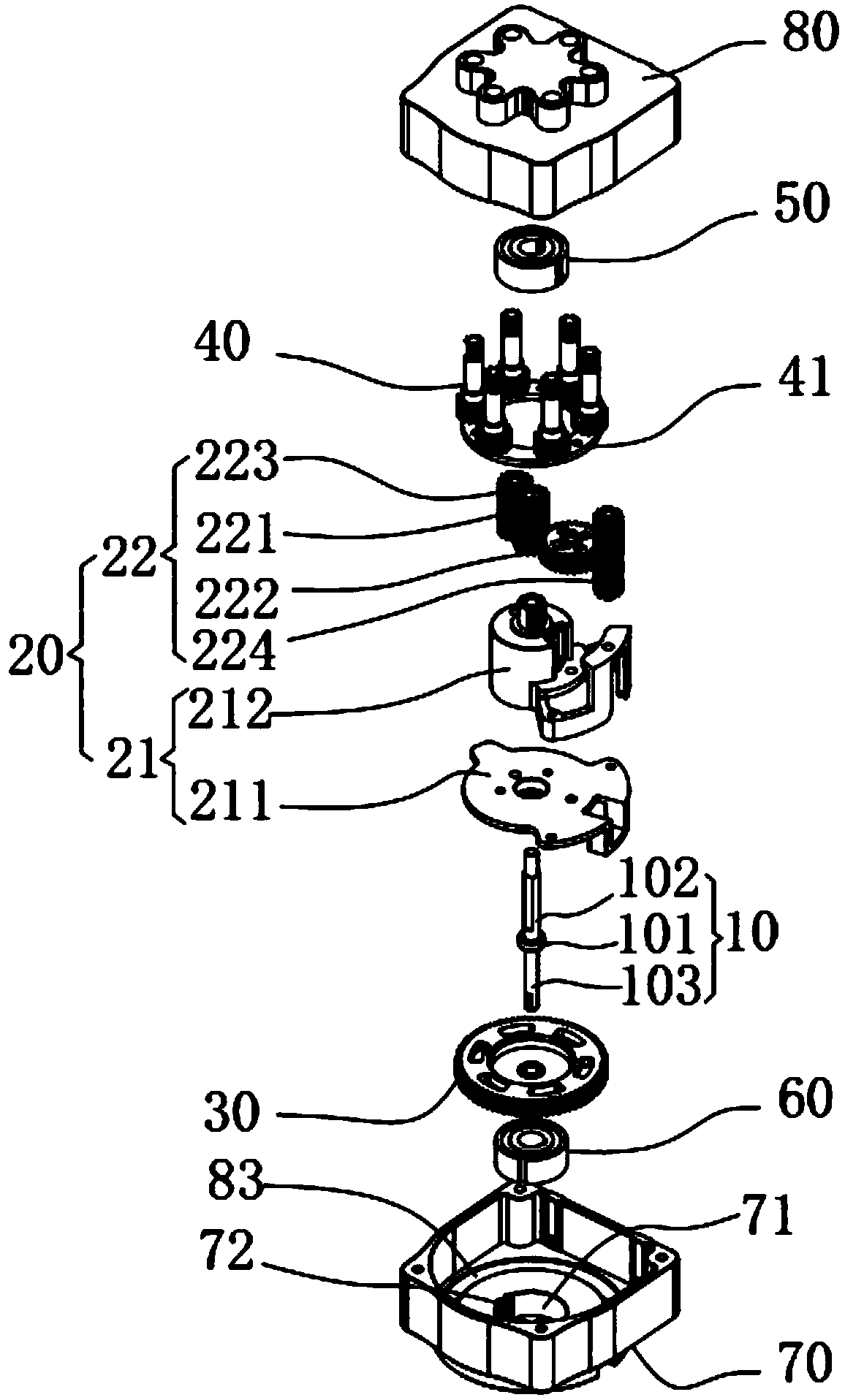
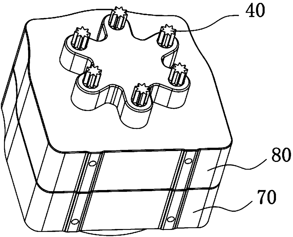
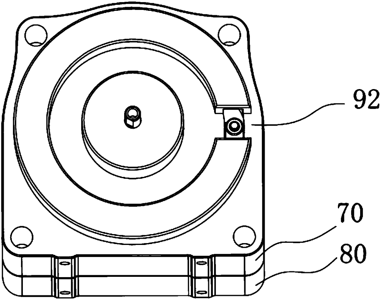
[0033] combine Figure 1 ~ Figure 3 As shown, an antenna transmission device disclosed in the present invention includes a driving shaft 10, a transposition assembly 20, a position selection gear 30, at least one output gear 40, a first one-way mechanism 50, a second one-way mechanism 60, and a front cover 70 and the rear cover 80, the front cover 70 and the rear cover 80 are fastened to each other, and a space is formed between the two after the fastening, except that the output gear 40 partially protrudes from the space, and other components are all arranged in the space. The drive shaft 10 is driven by an external drive unit (not shown in the figure), and the transposition assembly 20 can revolve in a certain direction to select a position under the drive of the drive shaft 10, and...


PUM


Abstract

The invention discloses an antenna transmission device comprising a driving shaft, a transposition component, a position selecting gear and at least one output gear; the transposition component is arranged on the driving shaft, and can be driven by the driving shaft to rotate only in the first direction and link to any one output gear, so that revolution and position selection are achieved; the position selecting gear is an outer gear ring arranged on the driving shaft and linking to the transposition component, and can be driven by the driving shaft to rotate only in the first direction, so that the transposition component is driven to rotate, and the output gear lining to the transposition component can be driven to output bi-directionally, namely in the forward direction or in the reverse direction. The antenna transmission device disclosed by the invention has the advantages of simple structure control, low cost, high integration level, easy assembly and replacement, and is suitable for scale industrialization, and the two-way output of a plurality of phase shifters can be controlled by a motor.

Description

technical field [0001] The invention relates to the field of mobile communication antennas, in particular to an antenna transmission device for adjusting the downtilt angle of a multi-frequency antenna in a base station antenna. Background technique [0002] The radiating surface of the mobile communication antenna is adjusted accordingly according to the change of the radiating unit of the antenna. Specifically, the phase shifter in the antenna is driven by the transmission device to adjust it. The phase, horizontal component, vertical component amplitude and other parameters of the antenna can achieve the effect of changing the coverage area. The electronically adjustable antenna interacts with the mechanical transmission device through the control unit to realize the transmission control of the antenna downtilt angle. [0003] In a traditional transmission system, different phase shifters are controlled by corresponding drive motors, and the rotational torque of each moto...

Claims


Application Information

Patent Timeline
Patent Type & Authority Applications(China)
IPC IPC(8): F16H1/32H01Q3/02
CPCH01Q3/02F16H1/32H01Q3/04
Inventor 桑建斌刘鹏蔡立绍李永忠
Owner PROSE TECH CO LTD
Why Eureka
Try Eureka