A power amplifier and linear regulator

A linear regulator and power amplification technology, applied in the electronic field, can solve problems such as oscillation, efficiency reduction, and push-pull effect deterioration, and achieve the effect of simple structure control, simple control, and high efficiency

Active Publication Date: 2018-03-23
ZTE CORP
View PDF3 Cites 0 Cited by
  • Summary
  • Abstract
  • Description
  • Claims
  • Application Information

AI Technical Summary

Problems solved by technology

The problem with this prior art is that the bandwidths of the two independent controllers 303 and 304 must be different in practical applications, otherwise conflicts are likely to cause oscillations, and when the bandwidth of one controller is low, the effect of push-pull will become worse. Efficiency is thus reduced and the bandwidth of the linear regulator is limited
[0007] In summary, the existing linear regulator technology is either not suitable for high-bandwidth and high-power applications, or there are many practical problems

Method used


Image

  • A power amplifier and linear regulator
  • A power amplifier and linear regulator
  • A power amplifier and linear regulator

Examples


Embodiment Construction

[0027] The linear regulator provided in this embodiment includes:

[0028] A power amplifying device, the power amplifying device includes a push-pull structure composed of two series connected N-type transistors, and a driving circuit, the driving circuit includes a P-type transistor;

[0029] The linear regulator may also include a preamplifier to provide the driving signal required by the power amplifier.

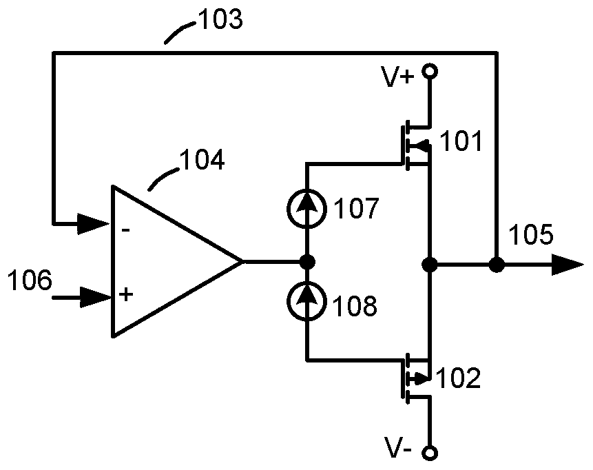
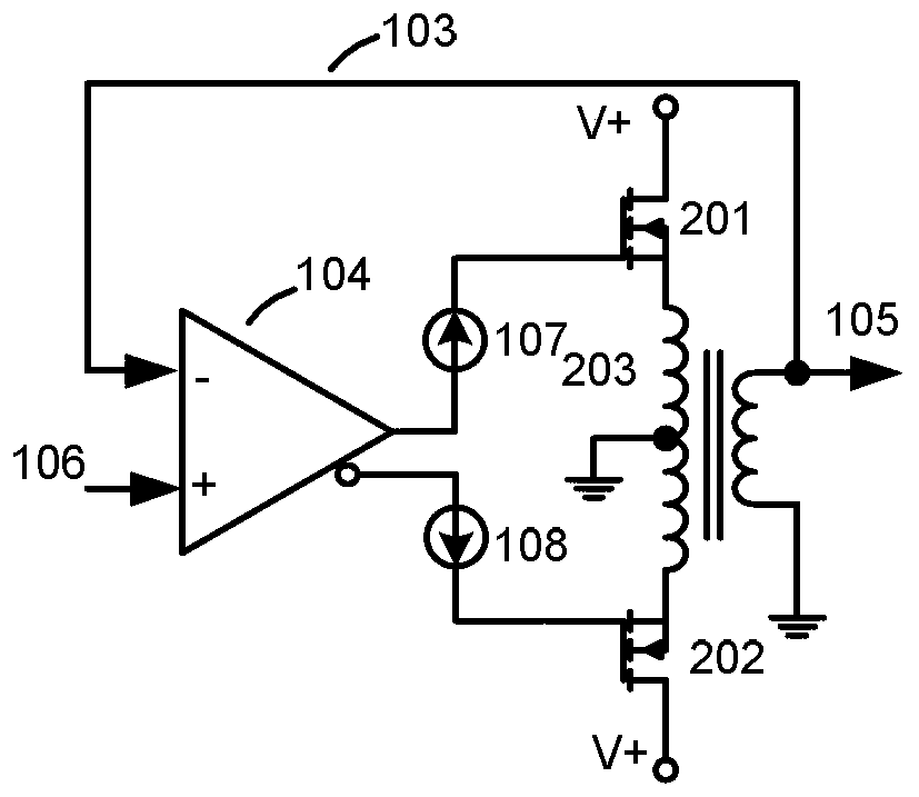
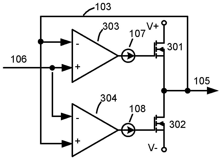
[0030] to solve figure 1 existing linear regulators in low bandwidth and figure 2 , image 3 In order to solve the problems of large volume, complicated control and low efficiency of existing linear regulators, this embodiment provides an implementation method of ultra-high bandwidth and high-power linear regulators.

[0031] Figure 4 It is a schematic diagram of a structure of the power amplifying device in the linear regulator of this embodiment, in Figure 4 Among them, the N-type transistor 401 (the first transistor) and the N-type transistor 402 (the second t...


PUM


Abstract

The invention discloses a power amplifying device and a linear regulator, comprising: a first transistor, a second transistor and a drive circuit for the second transistor, the first transistor is connected in series with the second transistor, and the drive circuit for the second transistor Including a third transistor, a compensation network and a voltage source, the first end of the third transistor is respectively connected to the drive signal end and the first transistor, the second end is connected to the connection end of the first transistor and the second transistor, and the third end The second transistor is connected to a compensation network respectively, and the compensation network is also connected to a voltage source. The push-pull structure composed of double N-type transistors provided by the present invention does not require transformer coupling, nor does it require independent control of the upper and lower transistors, and can realize the characteristics of simple structure and control, high efficiency, etc. In applications with high bandwidth and high power, there may be more problems.

Description

technical field [0001] The invention relates to the field of electronic technology, in particular to a power amplification device and a linear regulator. Background technique [0002] In electronic devices, there are many occasions where it is necessary to linearly amplify the signal to drive subsequent actuators, or as a power supply to supply power to subsequent devices. However, in some applications where the dynamic change of the load is very fast, or the bandwidth of the amplified signal is very high, the bandwidth of the linear power amplifying device is required to be very high. In particular, in the communication system, in order to achieve faster data transmission in the limited frequency spectrum, the amplitude of the modulated radio frequency signal varies greatly dynamically, which brings about a prominent problem that the efficiency of the radio frequency power amplifier is low, which becomes a key factor in improving the overall The bottleneck of communication...

Claims


Application Information

Patent Timeline
Patent Type & Authority Patents(China)
IPC IPC(8): H03F1/42H03F3/26
Inventor 王林国朱厚存张滨
Owner ZTE CORP
Why Eureka
Try Eureka