A tracking filling part for filling machine

A filling machine and filling technology, which is applied in the field of pharmaceutical packaging machinery and food, can solve the problems of difficulty in guaranteeing filling quality, influence of filling area, large movement stroke, etc., and achieve less friction particles, low cost, and simple structure control Effect

Active Publication Date: 2015-11-11
TRUKING TECH LTD
View PDF9 Cites 0 Cited by
  • Summary
  • Abstract
  • Description
  • Claims
  • Application Information

AI Technical Summary

Problems solved by technology

This form of tracking filling parts has the following defects: since the moving frame and the horizontal slide block are reciprocated in a straight line on the vertical axis and the horizontal axis through sliding bearings respectively, and the movement stroke is relatively large, during the work process, the sliding bearings The friction particles generated between the vertical axis and the horizontal axis are easily taken out of the sliding bearing, affecting the entire filling area, thereby bringing serious pollution risks and making it difficult to guarantee the filling quality

Method used


Image

  • A tracking filling part for filling machine
  • A tracking filling part for filling machine
  • A tracking filling part for filling machine

Examples


Embodiment 1

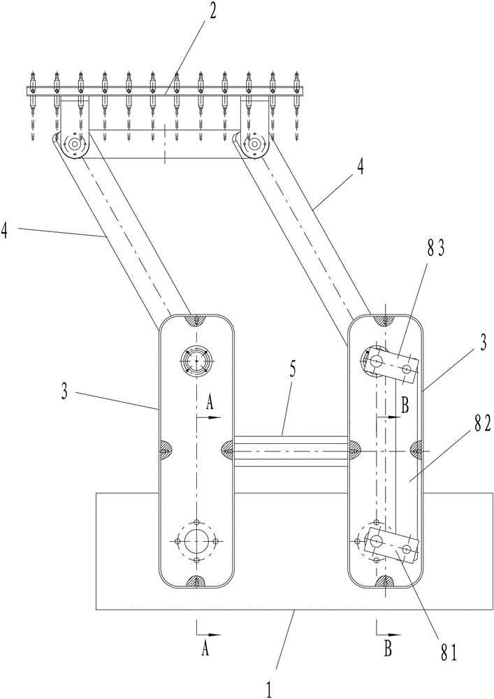
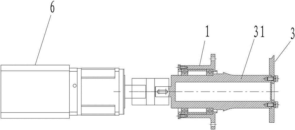
[0029] Such as figure 1 , Figure 4 As shown, the tracking filling part for the filling machine in this embodiment includes a frame 1, a needle filling frame assembly 2, two first swing arms 3 hinged on the frame 1 and a needle filling frame assembly hinged There are two second swing arms 4 on the 2, and the needle filling frame assembly 2 is provided with filling needles for filling. The first swing arm 3 and the second swing arm 4 located on the same side are hinged, and a connecting rod 5 is hinged between the two first swing arms 3 . One of the first swing arms 3 is connected with a first driving mechanism for driving the first swing arm 3 to swing around the frame 1, and one of the second swing arms 4 is connected with a drive mechanism for driving the second swing arm 4 to swing around the first swing arm 3. the second drive mechanism. The frame 1, the connecting rod 5 and the two first swing arms 3 form a parallelogram mechanism, and the needle irrigation frame assem...

Embodiment 2

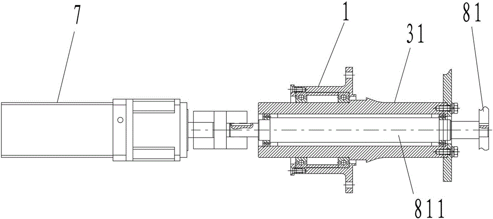
[0037] Figure 7 to Figure 11 Embodiment 2 of the present invention is shown, the structure of this embodiment is basically the same as that of Embodiment 1, the difference is: see Figure 7 , Figure 9 , Figure 11 , the second drive mechanism includes a second motor 7 and a fourth rod 84 and a fifth rod 85 that are hinged, the second motor 7 is installed on the frame 1, and the output shaft of the second motor 7 is connected to the fourth rod 84 It is fixedly connected and can drive the fourth rod 84 to rotate, and the fifth rod 85 is hinged to one of the second swing arms 4 . When working, the second motor 7 drives the fourth rod 84 to swing, and the fourth rod 84 drives the second swing arm 4 to swing through the fifth rod 85 . Compared with Embodiment 1, the structure of the second driving mechanism of this embodiment is simpler. The principle of this embodiment is the same as that of Embodiment 1, and will not be repeated here.


PUM


Abstract

The invention discloses a tracking filling part for a filling machine. The tracking filling part comprises a rack, a filling needle frame assembly, two first swinging arms and two second swinging arms, wherein the two first swinging arms are hinged to the rack; the two second swinging arms are hinged to the filling needle frame assembly; the first swinging arm and the second swinging arm which are on the same side are hinged with each other; a connecting rod is hinged between the two first swinging arms or between the two second swinging arms; at least one of the first swinging arms is connected with a first driving mechanism which is used for driving the at least one first swinging arm to swing around the rack; at least one of the second swinging arms is connected with a second driving mechanism which is used for driving the at least one second swinging arm to swing around the corresponding first swinging arm; the rack, the connecting rod and the two first swinging arms form a parallelogram mechanism, and the filling needle frame assembly and the two second swinging arms form another parallelogram mechanism; or, the filling needle frame assembly, the connecting rod and the two second swinging arms form a parallelogram mechanism, and the rack and the two first swinging arms form another parallelogram mechanism. The tracking filling part for the filling machine has the advantages of being simple in structure control, low in cost, low in pollution risk and the like.

Description

technical field [0001] The invention mainly relates to the field of food and medicine packaging machinery, in particular to a tracking filling part for a filling machine. Background technique [0002] At the filling station of the filling machine, since the bottle body is continuously conveyed forward, the tracking and filling parts are required to be able to realize the four functional actions of tracking down and inserting into the bottle mouth, tracking filling, rapid ascent and rapid return. All functional movements can be decomposed into horizontal tracking movement and vertical lifting movement, and the four functional movements constitute a movement cycle. Most of the existing tracking filling components use two sets of servo motors to respectively drive the moving frame for vertical lifting motion and the horizontal slider for horizontal tracking motion to complete the periodic actions of the needle filling frame assembly. This form of tracking filling parts has the...

Claims


Application Information

Patent Timeline
Patent Type & Authority Patents(China)
IPC IPC(8): B67C3/26
Inventor 王业洲许海文杨灿文
Owner TRUKING TECH LTD
Why Eureka
Try Eureka