Underground pipeline measuring device and application method thereof
A technology for measuring equipment and underground pipelines, applied in the direction of mechanical equipment, special pipes, pipe components, etc., can solve the problems of large interference, slow measurement speed, hidden safety hazards, etc., achieve stable traction direction, avoid uneven tension, and ensure accuracy Effect
- Summary
- Abstract
- Description
- Claims
- Application Information
AI Technical Summary
Problems solved by technology
Method used
Image
Examples
Embodiment 1
[0032] This embodiment mainly introduces the basic composition of an underground pipeline measurement device.
[0033] An underground pipeline measuring device, the measuring device includes a traction machine 1 and a measuring machine.
[0034] as attached figure 1 As shown, the tractor 1 includes a chassis 11 and a traction unit 12, and the traction unit 12 is arranged on the chassis 11 through a lifting device 13; the lifting device 13 can realize the adjustment of the vertical position of the traction unit 12 on the chassis 11; The chassis 11 is connected to the traction part 12 through a cable 14 . The lifting device 13 is preferably a lifting rod.
[0035] Further, the chassis 11 is provided with wheels 15 and crawlers 16, the wheels 15 are installed on both sides of the chassis 11, the wheels 15 are divided into driving wheels and driven wheels, and the crawlers 16 are sleeved on the wheels. The chassis 11 is provided with a power supply module, a power module, and a...
Embodiment 2
[0041] This embodiment is carried out on the basis of the foregoing embodiment 1, and mainly introduces the composition and structure of the measuring machine of the present invention.
[0042] The measuring machine includes an outer cylinder 21 , an inner cylinder 22 and an extension cylinder 23 .
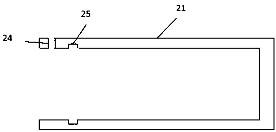
[0043] Further, as attached figure 2 As shown, the outer cylinder 21 is a hollow cylinder with one end as a closed end and one end as an open end. A buckle hole 24 is provided on the outer cylinder 21 near the open end, and a first seal is also provided on the inner circumference of the outer cylinder. A ring groove 25 , the first seal ring groove 25 is located inside the buckle hole 24 at a position adjacent to the buckle hole 24 .
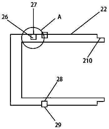
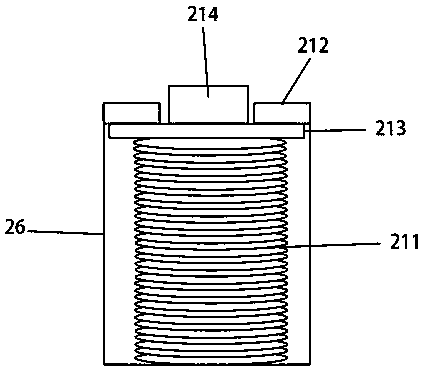
[0044] Further, as attached image 3 As shown, the inner cylinder 22 is a hollow cylinder with one end as a closed end and one end as an open end. A buckle groove 26 is provided on the inner cylinder 22 near the closed end, and an internal thread ...
Embodiment 3
[0050] This embodiment is carried out on the basis of the foregoing embodiment one or two, and mainly introduces the tension structure of the present invention.
[0051] as attached Image 6 As shown, a first fixed plate 216 is hooped on the circumference of the outer cylinder 21 near the open end, and a tensioning mechanism is provided on the closed end of the outer cylinder 21, and the tensioning mechanism includes a tensioning motor 217 and a rotating shaft 218, the rotating shaft 218 is connected to the tensioning motor 217 and driven by the tensioning motor 217; one end of the tensioning motor 217 is connected to the closed end of the outer cylinder 21, and the other end is provided with a second fixing plate 219, the central position of the second fixing plate 219 is provided with a circular hole 220, the rotating shaft 218 passes through the second fixing plate 219 and connects with the tensioning motor 217, and the rotating shaft 218 is provided with a screw thread Th...
PUM
 Abstract
Description
Claims
Application Information
 - R&D
- Intellectual Property
- Life Sciences
- Materials
- Tech Scout
- Unparalleled Data Quality
- Higher Quality Content
- 60% Fewer Hallucinations
Browse by: Latest US Patents, China's latest patents, Technical Efficacy Thesaurus, Application Domain, Technology Topic, Popular Technical Reports.
© 2025 PatSnap. All rights reserved.Legal|Privacy policy|Modern Slavery Act Transparency Statement|Sitemap|About US| Contact US: help@patsnap.com


