Oil return control device, air conditioning system and oil return control method of air conditioning system

A technology for oil return control and heat exchange system, which is applied to refrigerators, refrigeration components, refrigeration and liquefaction, etc. It can solve the problems of increasing equipment and control costs, unsuitable for dual-temperature air conditioning systems, and low operational reliability. Long service life, not easy to wear, and the effect of reducing the exhaust oil discharge rate

Active Publication Date: 2018-06-19
GREE ELECTRIC APPLIANCES INC
View PDF6 Cites 39 Cited by
  • Summary
  • Abstract
  • Description
  • Claims
  • Application Information

AI Technical Summary

Problems solved by technology

However, this oil return scheme is not applicable to such figure 1 The double-suction and double-row compressor shown, because the compressor contains two pairs of independent suction and discharge pipes, corresponding to different suction and discharge pressures, returns the lubricating oil to the compressor by utilizing the pressure difference between suction and discharge. It will increase the cost of equipment and control; at the same time, due to the special structure of the compressor, the oil discharge rate of the lower cylinder is much higher than that of the upper cylinder, and most of the lubricating oil is carried out through the exhaust of the lower cylinder. The oil return scheme of air return to oil will cause the lower cylinder of the compressor to run without oil and wear, so the existing oil return scheme is not suitable for dual-temperature air-conditioning systems with two-cylinder parallel compressors
[0004] In the prior art, there are defects such as easy wear of the lower cylinder, short service life and low operational reliability

Method used


Image

  • Oil return control device, air conditioning system and oil return control method of air conditioning system
  • Oil return control device, air conditioning system and oil return control method of air conditioning system
  • Oil return control device, air conditioning system and oil return control method of air conditioning system

Examples


Embodiment Construction

[0043] In order to make the purpose, technical solution and advantages of the present invention clearer, the technical solution of the present invention will be clearly and completely described below in conjunction with specific embodiments of the present invention and corresponding drawings. Apparently, the described embodiments are only some of the embodiments of the present invention, but not all of them. Based on the embodiments of the present invention, all other embodiments obtained by persons of ordinary skill in the art without making creative efforts belong to the protection scope of the present invention.

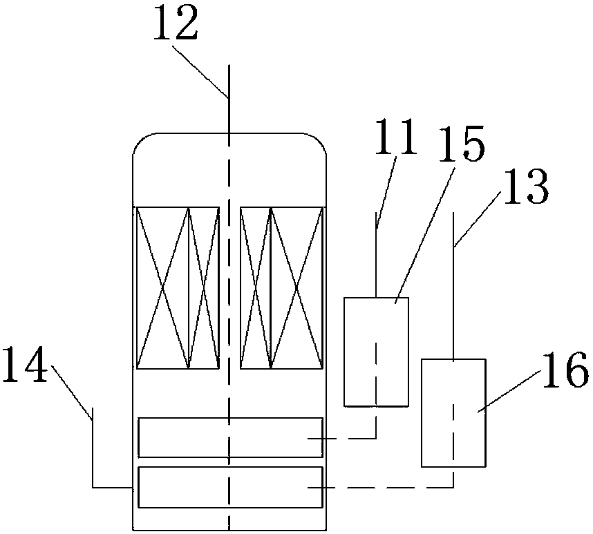
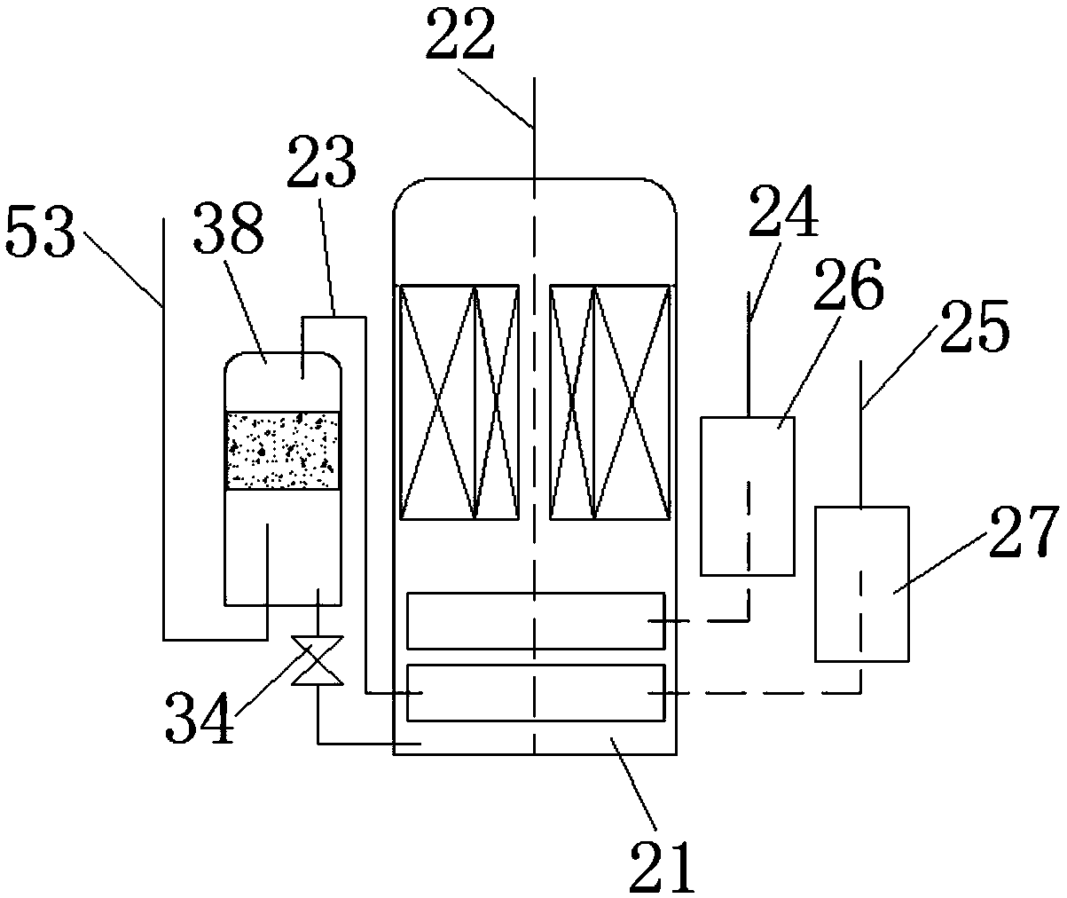
[0044] According to an embodiment of the present invention, an oil return control device (for example: an oil return control device for a compressor with a double-suction and double-row structure) is provided, such as figure 2 and Figure 9 A schematic structural view of an embodiment of the oil return control device of the present invention is shown. The oil r...


PUM


Abstract

The invention discloses an oil return control device, an air conditioning system and an oil return control method of the air conditioning system. The oil return control device comprises an oil separation mechanism and an oil return control assembly, wherein the oil separation mechanism is arranged at an exhaust port of a lower row of exhaust cylinders in a compressor comprising two or more parallel cylinders, and is used for separating and obtaining lubricating oil from exhaust gas of the lower row of exhaust cylinders, and the oil return control assembly is arranged between the oil separationmechanism and an oil pool at the bottom of the compressor, and is used for controlling the lubricating oil to return to the oil pool according to the pressure difference between exhaust ports of thetwo or more exhaust cylinders in the compressor. According to the scheme, the defects that in the prior art, a lower cylinder is prone to wear, short in service life, low in running reliability and the like can be overcome, so that the beneficial effects that the lower cylinder is not prone to wear, long in service life and high in running reliability are achieved.

Description

technical field [0001] The invention belongs to the technical field of air-conditioning, and in particular relates to an oil return control device, an air-conditioning system and an oil return control method thereof, in particular to an oil return control device of a dual-cylinder parallel compressor for a dual-temperature air conditioner, which has the oil return control device An air conditioning system, and an oil return control method for the air conditioning system. Background technique [0002] Existing air-conditioning systems usually use a single-suction single-row compressor, which forms a refrigeration cycle with indoor and outdoor single-row or multi-row heat exchangers to heat or cool indoor air to meet the comfort requirements of the indoor environment. Since the air conditioning system has only one pair of suction and exhaust ports connected to the indoor and outdoor heat exchangers, the air conditioning system can only achieve one evaporation temperature and c...

Claims


Application Information

Patent Timeline
Patent Type & Authority Applications(China)
IPC IPC(8): F25B43/02F25B41/00F25B49/02F25B41/20F25B41/34F25B41/40
CPCF25B43/02F25B49/02F25B2700/21155F25B41/40Y02B30/70
Inventor 吕如兵郑波方金升
Owner GREE ELECTRIC APPLIANCES INC
Why Eureka
Try Eureka