A white light LED package structure and a white light source system
A technology of LED packaging and white light source, applied in semiconductor devices, electrical components, circuits, etc., can solve problems such as large wavelength difference, reduced light efficiency, and large Stokes loss
- Summary
- Abstract
- Description
- Claims
- Application Information
AI Technical Summary
Problems solved by technology
Method used
Image
Examples
Embodiment 1
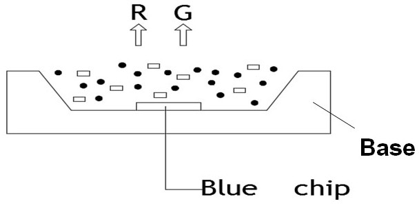
[0045] Such as Figure 5As shown, the present embodiment provides a white LED packaging structure, including: a base material (Base); the LED chip is located on the base material; the wavelength conversion material layer is located on the LED chip; wherein the LED chip is selected from a Violet chip ) and a blue chip (Blue chip), the wavelength of the purple chip is 385~425nm, preferably 410~420nm, the wavelength of the blue chip is 440~460nm, preferably 445~460nm, the wavelength conversion material layer can include wavelength conversion materials of two wavelengths, wherein One kind of wavelength conversion material is excited by the violet LED chip, and the emission spectrum wavelength is between 440 and 600nm. The other wavelength conversion material is excited by the blue light chip chip, and the emission spectrum wavelength is between 500 and 700nm. At 450-700nm, the wavelength conversion material layer absorbs the light emitted by the LED chip to emit white light.
[0...
Embodiment 2
[0053] Such as Figure 7 As shown, the difference from Example 1 is that the G phosphor and the R phosphor of this embodiment are mixed and covered on the blue light chip, while the B phosphor is alone covered on the purple light chip. Specifically, the wavelength of the purple light chip is 410nm~420nm, and the wavelength of the blue light chip is 445nm~460nm. The excitation wavelength of B phosphor is 390nm, which can better absorb violet light and emit blue light with a wavelength of about 460nm. G phosphor can choose Lu 3 al 5 o 12 : Ce 3+ Phosphors: The excitation wavelength is 450nm, LuAG hardly absorbs violet light, and the emission wavelength is about 550nm. R phosphor can choose AEC:Eu 2+ (AE=Ca and Sr) Phosphors, among which AE=Ca has the best effect: the excitation wavelength is around 450nm, and the excitation efficiency is high (higher than 80%). Under the condition of 410nm~420nm, the wavelength intensity is small, and the excitation efficiency Low (less ...
Embodiment 3
[0058] Such as Figure 10 As shown, the difference from Example 1 is that the GY (yellow-green) phosphor and B phosphor of this embodiment are mixed and covered on the purple light chip, while the R phosphor is alone covered on the blue light chip. Specifically, the wavelength of the purple light chip is 410~420nm, and the wavelength of the blue light chip is 445~460nm. The excitation wavelength of B phosphor is 390nm, which can better absorb violet light and emit blue light with a wavelength of about 460nm. GY phosphor can choose Eu-doped alkaline earth silicate Phosphors: the maximum excitation wavelength is 410nm, and the excitation efficiency reaches the highest between emission wavelength 500~600nm. R phosphor can choose AEC:Eu 2+(AE=Ca andSr) Phosphors, among which AE=Ca has the best effect: the excitation wavelength is around 450nm, and under the condition of 410~420nm, the wavelength intensity is small and the excitation efficiency is low (less than 70%); the emissio...
PUM
| Property | Measurement | Unit |
|---|---|---|
| wavelength | aaaaa | aaaaa |
| wavelength | aaaaa | aaaaa |
| wavelength | aaaaa | aaaaa |
Abstract
Description
Claims
Application Information
 - R&D
- Intellectual Property
- Life Sciences
- Materials
- Tech Scout
- Unparalleled Data Quality
- Higher Quality Content
- 60% Fewer Hallucinations
Browse by: Latest US Patents, China's latest patents, Technical Efficacy Thesaurus, Application Domain, Technology Topic, Popular Technical Reports.
© 2025 PatSnap. All rights reserved.Legal|Privacy policy|Modern Slavery Act Transparency Statement|Sitemap|About US| Contact US: help@patsnap.com


