
Forging method of large and complex die forging of A-100 steel and design method of pre-forging part thereof

A design method and die forging technology, which is applied to household components, other household appliances, household appliances, etc., can solve the problems of increasing the deformation of the rod, uneven deformation of the final forging, and large differences in the structure and performance of the forging

Active Publication Date: 2018-06-22
中国第二重型机械集团德阳万航模锻有限责任公司
View PDF3 Cites 2 Cited by
  • Summary
  • Abstract
  • Description
  • Claims
  • Application Information

AI Technical Summary

Problems solved by technology

Most of the complex die forgings for aircraft landing gear in China use a set of final forging dies for die forging in order to reduce the investment cost of dies, which leads to complex structures of blanks and large differences in the structure and performance of various parts of forgings; Although the design and manufacture of pre-forging dies are added to the complex die forgings for aircraft landing gear, in order to increase the deformation of the rods and reduce the difficulty of pre-forging, the pre-forgings of the landing gear rods are designed with square cross-sections
[0004] A-100 steel large and complex die forgings for aircraft landing gear adopt the traditional square cross-section design method. Although the design and pre-forging die processing process reduces the difficulty, it inevitably brings serious uneven deformation of the final forging. , the maximum deformation is more than 4 times of the minimum deformation, which in turn brings the difference in grain size of the forging > 3 grades, and it is easy to cause the forging to be scrapped due to mixed crystals
[0005] A-100 steel large and complex die forging pre-forging adopts the traditional square cross-section design method, which may easily lead to longer material swing time in the final forging process, lower initial forging temperature, greater die wear, and billet tilting during the forging process. Risks such as longitudinal folding and forging defects in the rod

Method used


Image

  • Forging method of large and complex die forging of A-100 steel and design method of pre-forging part thereof
  • Forging method of large and complex die forging of A-100 steel and design method of pre-forging part thereof
  • Forging method of large and complex die forging of A-100 steel and design method of pre-forging part thereof

Examples


Embodiment Construction

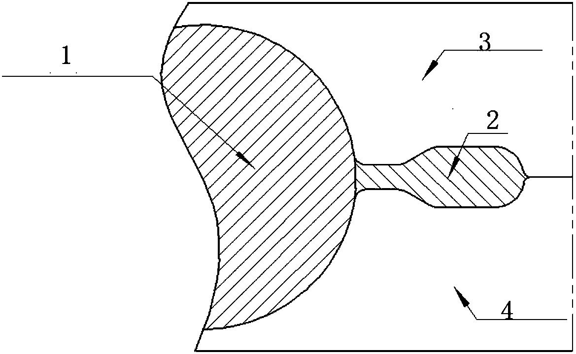
[0031] The section of the forging is mainly composed of the forging body 1 and the burrs 2 (see figure 1 ), the forming process of the forging goes through three steps: ①The blank is upset and formed; ②The forging contacts the bridge of the die and is further resisted; ③The forging is full. Therefore, in the design of pre-forgings, in order to reasonably distribute the deformation at different positions, it must be realized by optimizing the cross-sectional structure.

[0032] In order to explain the design method of this patent more clearly, the pre-forging design structure of a typical aircraft landing gear A-100 steel large-scale complex die forging is now used to further describe this patent.

[0033] The forging is a large and complex main lifting outer cylinder forging of a certain type of aircraft. It is a long-axis high-profile forging. figure 2 .

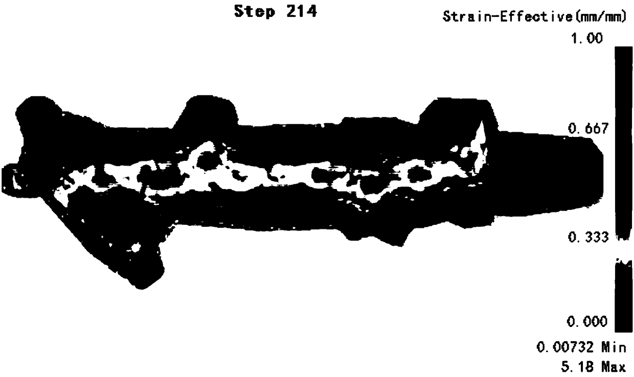
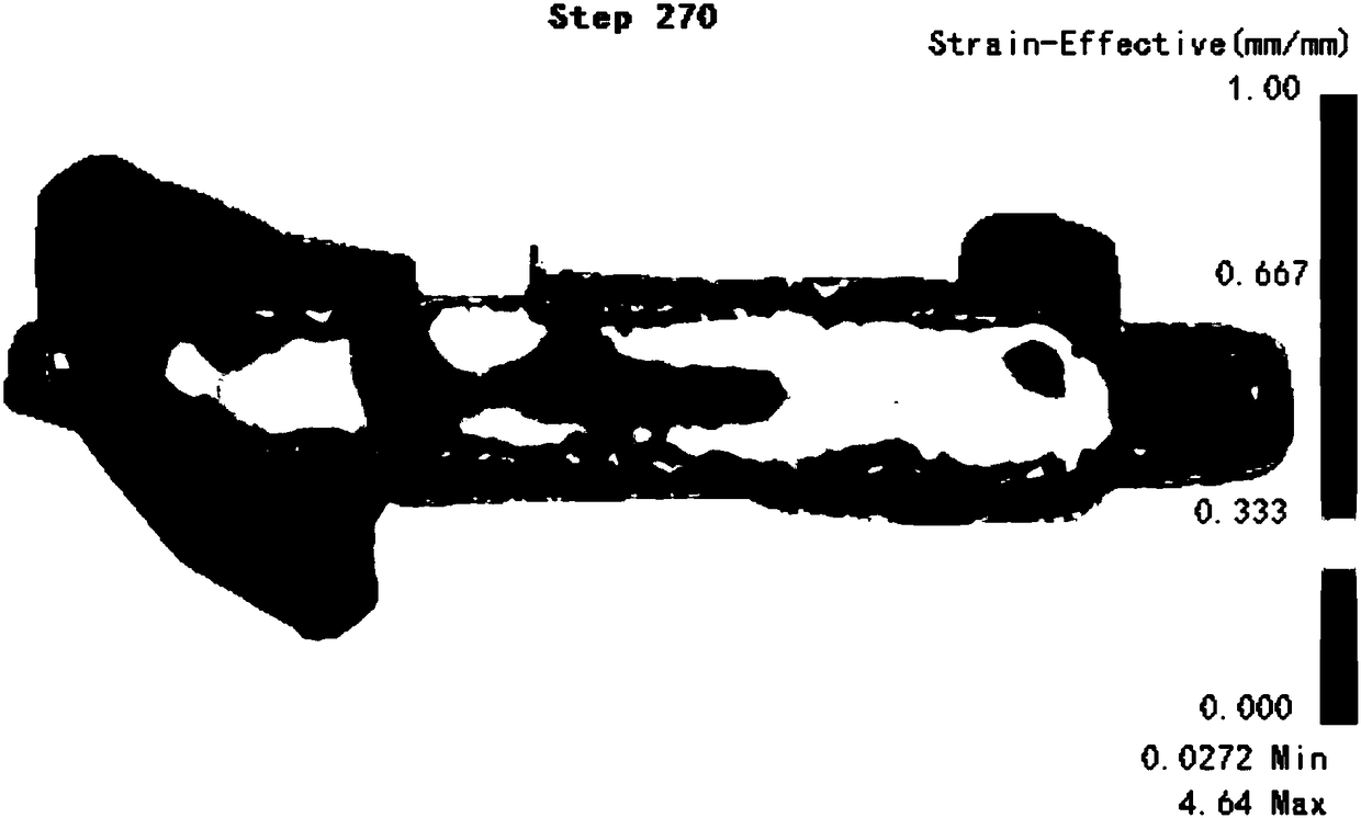
[0034] Such as image 3 and Figure 4 As shown, the traditional pre-forging adopts the square section design method,...


PUM


Abstract

The invention relates to the field of A-100 steel forging, and discloses a forging method of a large and complex die forging of A-100 steel and a design method of a pre-forging part thereof. The pre-forging part of the large and complex die forging of the A-100 steel adopts the design mode of a rhombic section of a rod portion, the deformation of a forging in the finish forging process can be increased to the maximum, and the deformation of the central portion of the rod portion of the forging can be >=25%; the grain size difference requirement of different positions of the forging is reducedto ensure that a grain grade differential grade of a finish forging is <=3; and meanwhile, the pre-forging part is quickly positioned, the blank in the forging process is prevented from tilting, and the filling of the forging is ensured.

Description

technical field [0001] The invention relates to the field of A-100 steel forging, in particular to a forging method of A-100 steel large complex die forging and a method for designing a pre-forging. Background technique [0002] The landing gear of modern aircraft, including large passenger aircraft and military aircraft, is mostly designed and manufactured with ultra-high-strength steel such as A-100 steel. The key technical indicators of forgings, mechanical properties and grain size, are more sensitive to the amount of deformation and the number of forging fires in the forging process. . In addition, because the large and complex die forgings for aircraft landing gear have the characteristics of large-scale (the weight of the forging is more than 1t), and the cross-sectional area changes greatly (the maximum can exceed 4 times), the difficulty factor of the forging is the most complex S4 level. The unreasonable design of the pre-forging can easily lead to problems such a...

Claims


Application Information

Patent Timeline
Patent Type & Authority Applications(China)
IPC IPC(8): B21K23/00
CPCB21K23/00
Inventor 孙朝远谢静闵武程立维
Owner 中国第二重型机械集团德阳万航模锻有限责任公司
Learn More