Eureka AIR delivers breakthrough ideas for toughest innovation challenges, trusted by R&D personnel around the world.

Elastic supporting bearing structure

An elastic support and bearing technology, applied in steering mechanism, electric steering mechanism, power steering mechanism, etc., can solve the problem that the steel ball of the elastic support bearing unit cannot be stably guided, the meshing position of the worm gear is wrong, and the force in the meshing area is uneven, etc. problem, to achieve the effect of simple structure, extended service life and low manufacturing cost

Pending Publication Date: 2018-06-22
WUXING HUAYANG ROLLING BEARING JIANGSU LITTLESWAN GROUP
View PDF14 Cites 1 Cited by
  • Summary
  • Abstract
  • Description
  • Claims
  • Application Information

AI Technical Summary

Problems solved by technology

In this process, the worm gear and worm unit not only has to bear the torque fluctuation when the single-click start, but also absorbs the vibration excitation from the road surface. These working conditions will cause the parts of the elastic support bearing unit to resonate, and the meshing position of the worm gear and worm is wrong. , the uneven force in the meshing area and the inability to stably guide the steel balls inside the related elastic support bearing unit, the gaskets produce relative rotation friction sound, the above problems will eventually be transformed into noise that reduces comfort
[0003] The existing elastic support bearing unit has a large number of components, and it is necessary to press the bracket, bearing, floating elastic block, and compression gasket together, and fix the bracket, bearing, floating elastic block, and compression gasket in the axial direction. Assembly requirements are high and manufacturing is difficult

Method used


Image

  • Elastic supporting bearing structure
  • Elastic supporting bearing structure
  • Elastic supporting bearing structure

Examples


Embodiment Construction

[0016] Below the present invention will be further described in conjunction with the embodiment in the accompanying drawing:

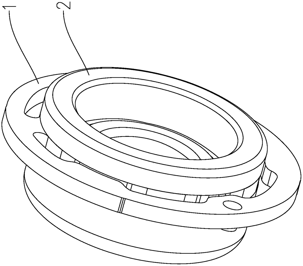
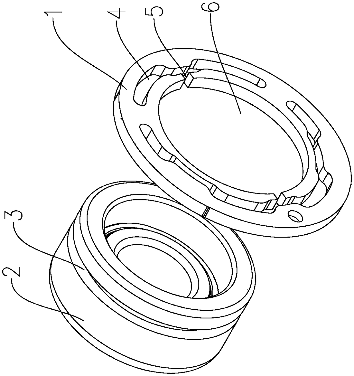
[0017] Such as Figure 1~4 As shown, the present invention mainly includes a floating elastic block 1 and a ball bearing 2. A stop groove 3 is provided on the outer peripheral surface of the ball bearing 2, and the floating elastic block 1 is embedded in the stop groove 3 of the ball bearing 2.

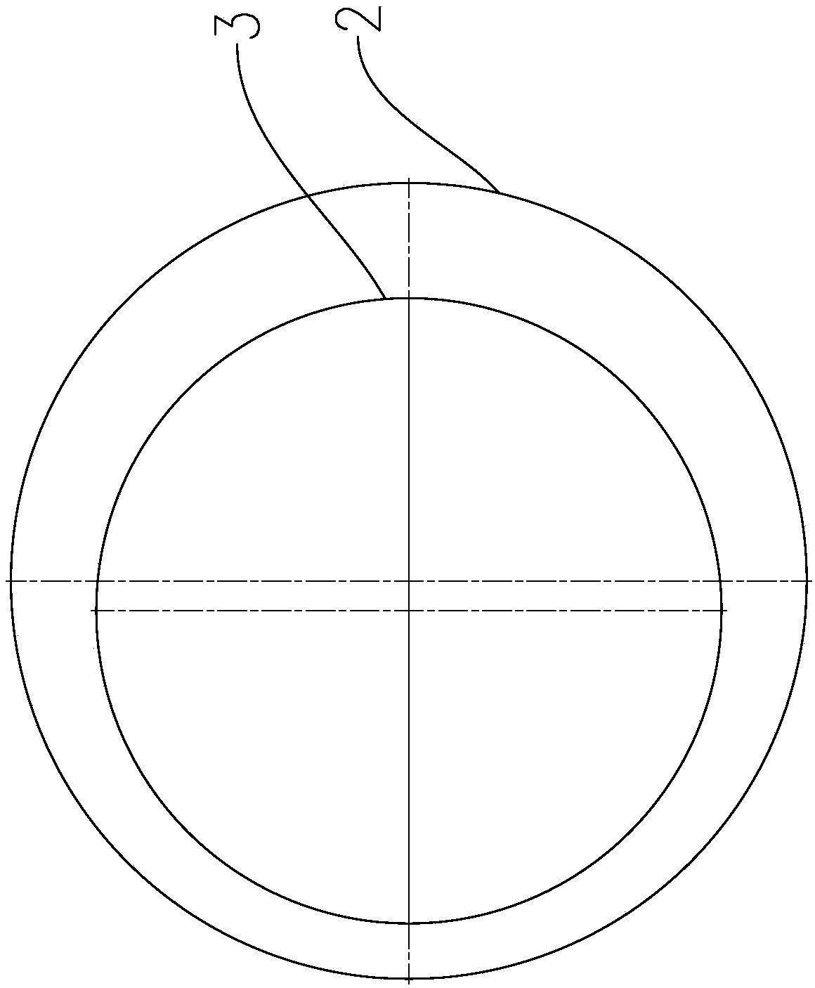
[0018] In order to prevent the floating elastic block 1 from freely rotating in the stop groove 3 of the ball bearing 2, the stop groove 3 is an eccentric groove, and the center of the circle where the stop groove 3 is located deviates from the circle center of the outer circumference of the ball bearing 2 by a certain distance.

[0019] The center of the floating elastic block 1 is provided with an installation cavity 6 , and at least one elastic groove 4 is arranged on the floating elastic block 1 , and the elastic groove 4 is arranged along the circumferent...


PUM


Abstract

The invention relates to a bearing structure, particularly to an elastic supporting bearing structure, and belongs to the technical field of the bearing structure. The elastic supporting bearing structure comprises a floating elastic block and a ball bearing; a locking slot is arranged on the surface of an outer circumference of the ball bearing, the floating elastic block is embedded in the locking slot of the ball bearing; an installing cavity is arranged in the center of the floating elastic block, and at least one elastic slot is arranged on the floating elastic block; a pressing slot is arranged between the installing cavity and the elastic slot, the pressing slot is connected with the installing cavity and the elastic slot. The elastic supporting bearing structure is simple, compactand reasonable in structure, low in manufacturing cost, and high in product stability; the transferred vibration can be completely absorbed by using the floating elastic block, the worm movement in crowd is prevented, the noise happening is reduced, the meshing stability of an electric power steering machine of an automobile is improved, and the service life is prolonged.

Description

technical field [0001] The invention relates to a bearing structure, in particular to an elastically supported bearing structure, which belongs to the technical field of bearing structures. Background technique [0002] When the electric power steering gear of the automobile is working, the power boost of the motor is amplified and transmitted to the mechanical steering gear through the meshing transmission of the worm gear to complete the steering action. In this process, the worm gear and worm unit not only has to bear the torque fluctuation when the single-click start, but also absorbs the vibration excitation from the road surface. These working conditions will cause the parts of the elastic support bearing unit to resonate, and the meshing position of the worm gear and worm is wrong. , the uneven force in the meshing area and the inability to stably guide the steel balls inside the relevant elastic support bearing unit, and the friction sound of the relative rotation of...

Claims


Application Information

Patent Timeline
Patent Type & Authority Applications(China)
IPC IPC(8): B62D3/04B62D5/04F16F15/04
CPCF16F15/04B62D3/04B62D5/0442
Inventor 李开元吴林强倪刚方苑王云霞王小明原跃平吴同浩
Owner WUXING HUAYANG ROLLING BEARING JIANGSU LITTLESWAN GROUP
Why Eureka
Eureka Blog
Learn More