Shockproof and anti-drop Bluetooth noise reduction earphone shell
A technology of noise reduction earphones and Bluetooth, which is applied in earpiece/earphone accessories, earphones to reduce environmental noise, and sounding equipment, etc. It can solve the problems of affecting the scope of application of Bluetooth earphone shells, poor shockproof and anti-drop effects, and damage, etc.
- Summary
- Abstract
- Description
- Claims
- Application Information
AI Technical Summary
Problems solved by technology
Method used
Image
Examples
Embodiment 1
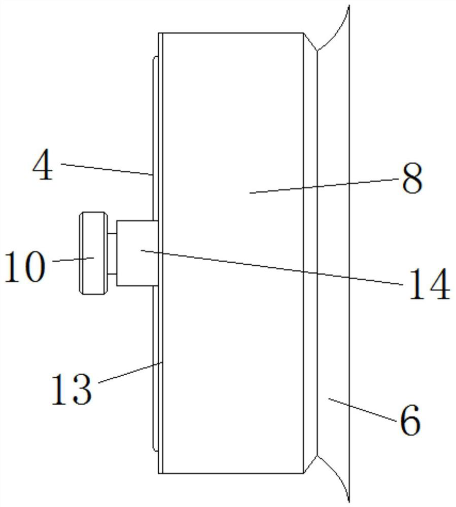
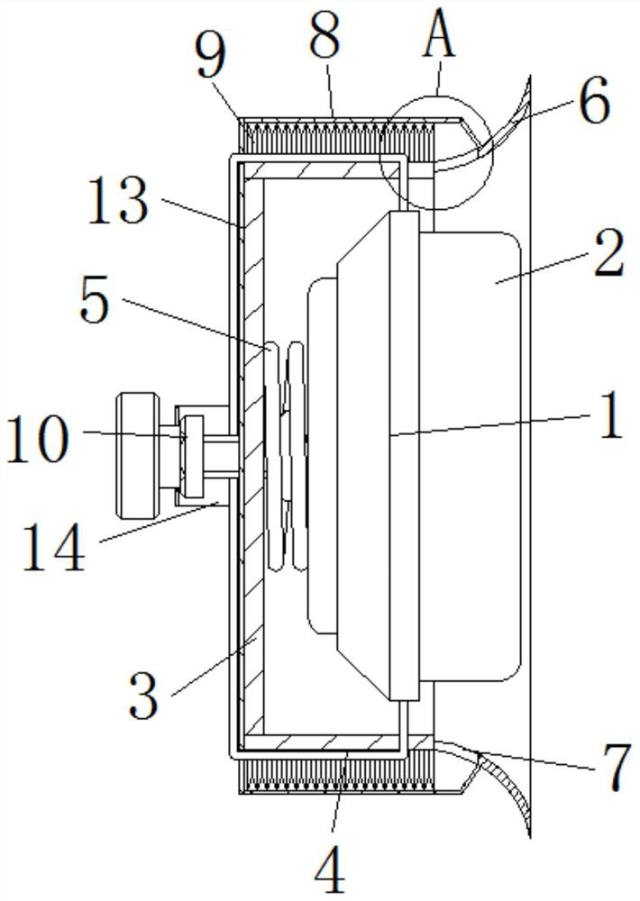
[0035] Such as Figure 1 to Figure 4 As shown, a shockproof and drop-proof Bluetooth noise-cancelling earphone case provided by the present invention includes a case 1;
[0036] The sponge ring 2 fixed on the right side of the housing 1;
[0037] The surface of the housing 1 is covered with a protective shell 3, and the left side of the protective shell 3 is provided with a traction rope 4, and the top and bottom ends of the traction rope 4 respectively extend to the outside of the protective shell 3 and penetrate into the interior of the protective shell 3, pulling Both ends of the rope 4 are fixedly connected to the surface of the housing 1 , and the left side of the housing 1 is fixedly connected to a compression spring 5 , and the side of the compression spring 5 away from the housing 1 is in contact with the inner wall of the protective case 3 .
[0038] refer to figure 1 , the right side of the protective shell 3 is fixedly connected with a rubber sleeve 6 surrounding ...
Embodiment 2
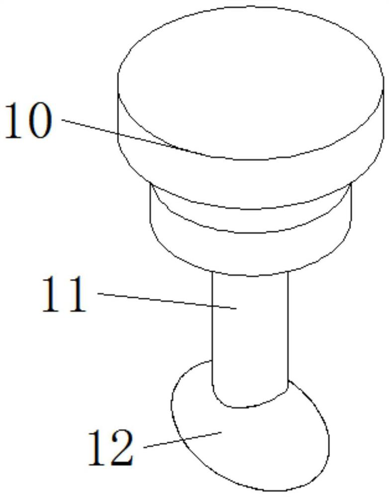
[0053] Such as Figure 5 and Figure 6 As shown, in the second embodiment, other structures remain unchanged, and the present invention provides another screw 11, the surface of the screw 11 is covered with a winding wheel 15 located on the left side of the protective shell 3, and the winding wheel 15 is positioned Inside the frame 14, the diameter of the winding wheel 15 is greater than the width of the positioning frame 14, and the traction rope 4 is wound on the surface of the winding wheel 15, and the left side of the winding wheel 15 is fixedly connected with a friction pad 16, and the left side of the friction pad 16 In contact with the right side of the running wheel 10, several push plates 17 are fixedly connected to the surface of the winding wheel 15.
[0054] By setting the winding wheel 15 sleeved on the surface of the screw rod 11, the traction rope 4 can be wound and wound, which is convenient for the user to flexibly adjust the length of the two ends of the tract...
Embodiment 3
[0057] Such as Figure 7 and Figure 9 As shown, in the third embodiment, other structures remain unchanged, and the present invention provides another protective shell 3, including openings 18 at the top and bottom of the protective shell 3, and the inside of the opening 18 is movably connected with a roller 19, and the roller The outer surface of 19 is in contact with the surface of winding wheel 15, and the top and bottom on the left side of protective shell 3 are fixedly connected with support 20, and the inner side of support 20 is movably connected with support wheel 22 by pin shaft 21, and the outer surface of support wheel 22 In contact with the surface of the traction rope 4, the front and back of the support wheel 22 are fixedly connected with a stop ring 23 positioned at the outside of the traction rope 4, and the left and right sides of the traction rope 4 surface are fixedly connected with a pull ring 23 positioned at the inside of the bracket 20. Ball 24.
[00...
PUM
 Abstract
Description
Claims
Application Information
 - R&D
- Intellectual Property
- Life Sciences
- Materials
- Tech Scout
- Unparalleled Data Quality
- Higher Quality Content
- 60% Fewer Hallucinations
Browse by: Latest US Patents, China's latest patents, Technical Efficacy Thesaurus, Application Domain, Technology Topic, Popular Technical Reports.
© 2025 PatSnap. All rights reserved.Legal|Privacy policy|Modern Slavery Act Transparency Statement|Sitemap|About US| Contact US: help@patsnap.com


