Automatic labeling machine

A labeling machine, automatic technology, applied in the direction of labeling machine, labeling, packaging, etc., can solve the problems of production efficiency, lack of adjustment function, limit and other problems, and achieve the effect of improving accuracy, fast action and high efficiency

Pending Publication Date: 2018-06-22
常州五王电机有限公司
View PDF7 Cites 1 Cited by
  • Summary
  • Abstract
  • Description
  • Claims
  • Application Information

AI Technical Summary

Problems solved by technology

Labeling machine is an indispensable part of modern packaging. At present, the types of labeling machines produced in my country are gradually increasing, and the technical level has also been greatly improved. It has shifted from the backward situation of manual and semi-automatic labeling to automated high-speed labeling machines. However, the existing labeling machines do not have flexible adjustment functions, and the existing labeling machines can only be used to label packaging containers of a specific height, which greatly limits the use of labeling machines. Bring great trouble to the improvement of production efficiency

Method used


Image

  • Automatic labeling machine

Examples


Embodiment 1

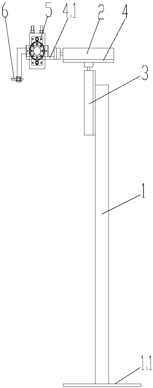
[0012] Embodiment 1: as figure 1 The shown automatic labeling machine includes a column 1, a lifting cylinder 3, a horizontal cylinder 2, a swing cylinder 5, and a vacuum suction cup 6. The lifting cylinder 3 is vertically arranged on the top of the column 1, and the piston rod of the lifting cylinder 3 is upward , the horizontal cylinder 2 is horizontally arranged at the front end of the piston rod of the lifting cylinder 2, the horizontal cylinder 2 is connected with the piston rod of the lifting cylinder 3 with the first connecting plate 4, the front end of the piston rod of the horizontal cylinder 2 is provided with a second connecting plate 4.1, and the swing cylinder 5 is fixed on the connection plate 4.1, and the vacuum suction cup 6 is set at the end of the L-shaped output shaft of the swing cylinder 5. The L-shaped output shaft increases the swing radius, which is convenient for labeling processing of different packaging containers, and changes the The swing position ...

Embodiment 2

[0013] Embodiment 2: as figure 1 The shown automatic labeling machine includes a column 1, a lifting cylinder 3, a horizontal cylinder 2, a swing cylinder 5, and a vacuum suction cup 6. The lifting cylinder 3 is vertically arranged on the top of the column 1, and the piston rod of the lifting cylinder 3 is upward , the horizontal cylinder 2 is horizontally arranged at the front end of the piston rod of the lifting cylinder 2, the horizontal cylinder 2 is connected with the piston rod of the lifting cylinder 3 with the first connecting plate 4, the front end of the piston rod of the horizontal cylinder 2 is provided with a second connecting plate 4.1, and the swing cylinder 5 is fixed on the connection plate 4.1, and the vacuum suction cup 6 is set at the end of the Z-shaped output shaft of the swing cylinder 5. The Z-shaped output shaft increases the swing radius, which is convenient for labeling processing of different packaging containers, and changes the The swing position ...


PUM


Abstract

The invention relates to the technical field of labeling machines, in particular to an automatic labeling machine. The automatic labeling machine comprises a vertical column, air cylinders, a swingingair cylinder and a vacuum suction cup. The air cylinders comprise a horizontal air cylinder and a lifting air cylinder, the lifting air cylinder is arranged at the top end of the vertical column, a lifting air cylinder piston rod faces up, and the horizontal air cylinder is horizontally arranged and connected with the front end of the lifting air cylinder piston rod through a first connecting plate; and a second connecting plate is arranged at the front end of a horizontal air cylinder piston rod, the swinging air cylinder is fixed to the second connecting plate, the vacuum suction cup is detachably arranged at the end of an output shaft of the swinging air cylinder, the working height and the working position are conveniently adjusted, and the production efficiency can be promoted to improve.

Description

technical field [0001] The invention relates to the technical field of labeling machines, in particular to an automatic labeling machine. Background technique [0002] A labeling machine is a device that pastes labels (paper or metal foil) on specified packaging containers. Labeling machine is an indispensable part of modern packaging. At present, the types of labeling machines produced in my country are gradually increasing, and the technical level has also been greatly improved. It has shifted from the backward situation of manual and semi-automatic labeling to automated high-speed labeling machines. However, the existing labeling machine does not have a flexible adjustment function, and the existing labeling machine can only be used to label packaging containers of a specific height, which greatly limits the use of the labeling machine. It brings great trouble to the improvement of production efficiency. Contents of the invention [0003] The technical problem to be sol...

Claims


Application Information

Patent Timeline
IPC IPC(8): B65C9/14
CPCB65C9/14
Inventor 刘国杰陈俊杰
Owner 常州五王电机有限公司
Why Eureka
Try Eureka