Coating phosphating slag removal system

A phosphating and coating technology, applied in the direction of metal material coating process, etc., can solve problems such as pipeline blockage, avoid grinding, eliminate phosphating slag, and achieve good slag removal effect.

Active Publication Date: 2018-06-22
JINAN UNIVERSITY
View PDF10 Cites 3 Cited by
  • Summary
  • Abstract
  • Description
  • Claims
  • Application Information

AI Technical Summary

Problems solved by technology

[0003] The technical problem to be solved by the present invention is to provide a coating phosphating and slag removal system for the defects existing in the existing design technology. The utilization rate of liquid reduces the maintenance cost of related equipment

Method used


Image

  • Coating phosphating slag removal system
  • Coating phosphating slag removal system

Examples


Embodiment 1

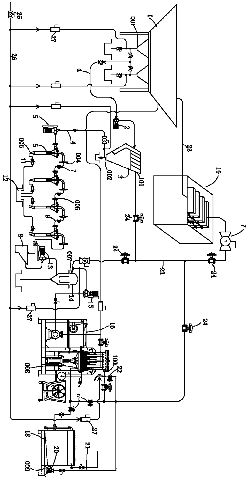
[0023] Reference attached figure 1, a coating phosphating slag removal system, including a phosphating tank 1, the phosphating tank 1 is connected to the phosphating precipitation tank 3 through a delivery pump 2, specifically, the liquid outlet 001 of the phosphating tank 1 passes through The pipeline 4 is connected in series with the liquid outlet valve (not labeled in the drawings, a conventional manual butterfly valve is often used) and then connected to the delivery pump 2, and the delivery pump 2 is connected to the phosphating sedimentation tank 3 through the pipeline 4. The delivery pump 2 can The phosphating solution discharged along the liquid outlet 001 of the phosphating tank 1 is sent into the phosphating settling tank 3 for initial slag removal. The liquid outlet 002 of the phosphating sedimentation tank 3 is connected to several filters 6 in series through the pipeline 4 and the first delivery pump 5, and the phosphating solution outlet 004 of the filter 6 at th...

Embodiment 2

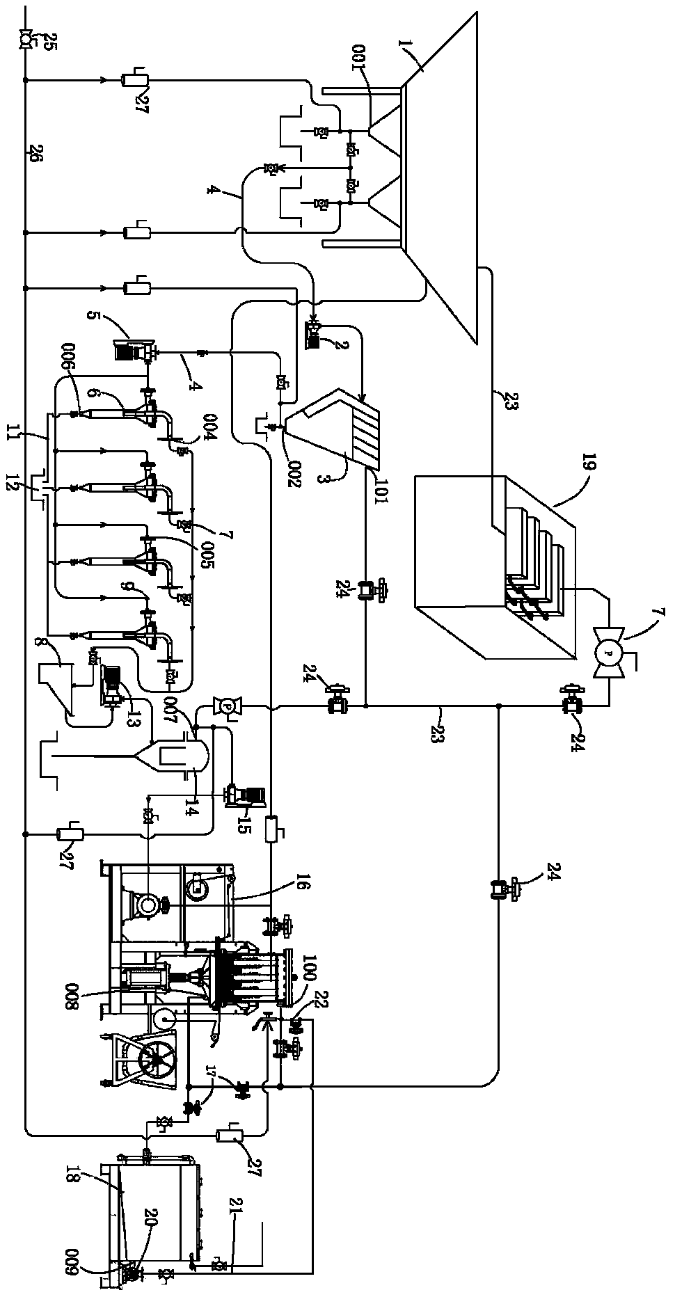
[0028] Reference attached figure 2 , a coating phosphating slag removal system, including a phosphating tank 1, the phosphating tank 1 is connected to the phosphating precipitation tank 3 through a delivery pump 2, specifically, the liquid outlet 001 of the phosphating tank 1 passes through The pipeline 4 is connected in series with the liquid outlet valve (not labeled in the drawings, a conventional manual butterfly valve is often used) and then connected to the delivery pump 2, and the delivery pump 2 is connected to the phosphating sedimentation tank 3 through the pipeline 4. The delivery pump 2 can The phosphating solution discharged along the liquid outlet 001 of the phosphating tank 1 is sent into the phosphating settling tank 3 for initial slag removal. The liquid outlet 002 of the phosphating sedimentation tank 3 is connected to several filters 6 connected in parallel through the first transfer pump 5 through the pipeline 4, and the liquid inlets 005 of the several fi...


PUM


Abstract

The invention discloses a coating phosphating slag removal system. The system comprises a phosphating tank, the phosphating tank is connected with a phosphating settling tank, and the phosphating settling tank is connected with a first conveying pump through pipelines in series and a plurality of filters in parallel; the filters are connected with the phosphating concentrated solution storage tankthrough pipelines and a filter pump; the phosphating concentrated solution storage tank is connected with a reverse filter through pipelines and a second conveying pump, and the reverse filter is connected with the full-quantity filtering type slag removal machine through pipelines and a third conveying pump; the full-quantity filtering type slag removal machine is connected with a back cleaningdevice through a valve matching pipeline and / or a filter membrane assembly; the back cleaning device is further connected with a gas port and a liquid return port of the full-amount filtering type slag removal machine through a cleaning tube, a cleaning pump and the first valve and a back washing loop is formed cooperatively; the filter membrane component is connected with the phosphating precipitation tank, the reverse filter is connected with the first liquid outlet of the phosphorization settling tank, and a liquid outlet of the reverse filter and a clear phosphating solution flowing out ofa liquid outlet of the full-quantity filtering type slag removal machine are filtered by the filter membrane component and then sent back to the phosphating tank through a water return pipe.

Description

technical field [0001] The invention relates to the technical field of coating, in particular to a coating phosphating and slag removal system. Background technique [0002] For large industrial enterprises, painting and electrophoresis are the main production lines, especially for truck and automobile manufacturing enterprises. For coating and electrophoresis production lines, it is necessary to assemble a matching phosphating and slag removal system to meet production requirements. However, the deficiencies of the existing phosphating and slag removal systems of some enterprises are: first, poor slag removal effect, pipeline blockage, and serious liquid leakage, resulting in more particles attached to the surface of the workpiece after electrophoresis, which needs to be polished In order to ensure the smoothness of the product surface, the grinding process will affect the subsequent spraying quality of the processed parts; the second is that the existing plate and frame f...

Claims


Application Information

Patent Timeline
IPC IPC(8): C23C22/86
CPCC23C22/86
Inventor 郭洪飞李从东屈挺黄国全何智慧王坤楠顶万明
Owner JINAN UNIVERSITY
Why Eureka
Try Eureka