Filtering and lifting device and roller washing machine

A filter structure and water hole technology, which is applied to other washing machines, washing devices, textiles and paper making, etc., can solve the problems of poor washing effect of the drum washing machine, and achieve the goal of avoiding contact with clothes again, washing fully, and avoiding drain valve clogging Effect

Active Publication Date: 2018-06-22
SUZHOU SAMSUNG ELECTRONICS CO LTD +1
View PDF5 Cites 10 Cited by
  • Summary
  • Abstract
  • Description
  • Claims
  • Application Information

AI Technical Summary

Problems solved by technology

[0005] The purpose of the present invention is to provide a filter lifting device to solve the technical problem of the poor washing effect of the drum washing machine in the prior art

Method used


Image

  • Filtering and lifting device and roller washing machine
  • Filtering and lifting device and roller washing machine
  • Filtering and lifting device and roller washing machine

Examples


Embodiment 1

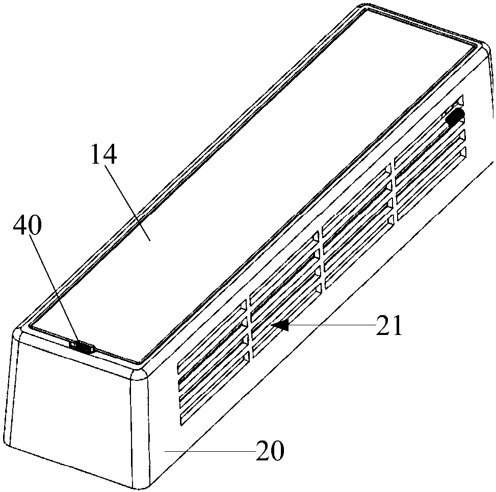
[0045] Such as Figure 1-15 As shown, the filter lifting device provided by the embodiment of the present invention includes: a housing 10 having an inner cavity, and the opposite sides of the housing 10 are respectively provided with water holes 13 along the direction in which the water flows through. There is a baffle 11, on the side of the casing 10 provided with a water hole 13 and / or on the baffle 11, at least part of the area is provided with a filtering structure 12; the baffle 11 swings to the inside of the casing 10 under the push of water flow and The water hole 13 is fully exposed, and the baffle plate 11 is driven by the water flow to swing to the outside of the housing 10 and cover the water hole 13 , so that water flows out of the inner cavity of the housing 10 through the filter structure 12 .

[0046] The filter lifting device of the embodiment of the present invention is installed in the inner cylinder of the drum washing machine. During the working process of...

Embodiment 2

[0059] In the filter lifting device, at least part of the area on the side of the housing 10 provided with the water hole 13 and / or on the baffle plate 11 is provided with the filter structure 12, that is to say, only the housing 10 may be provided with the filter structure 12. The filter structure 12 is provided on the side of the water hole 13 , or the filter structure 12 is provided only on the baffle 11 , or the filter structure 12 is provided on both the housing 10 and the baffle 11 . Filtering structure 12 can be selected filter screen, simple in structure, low in cost, easy to install.

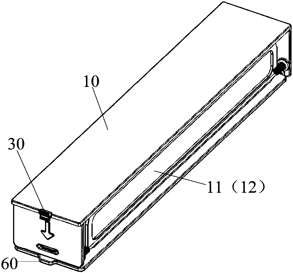
[0060] Such as Figure 1-6 As shown, in the second embodiment, the filtering structure 12 is installed on the baffle 11 , and the bottom or top of the baffle 11 is hinged to the housing 10 .

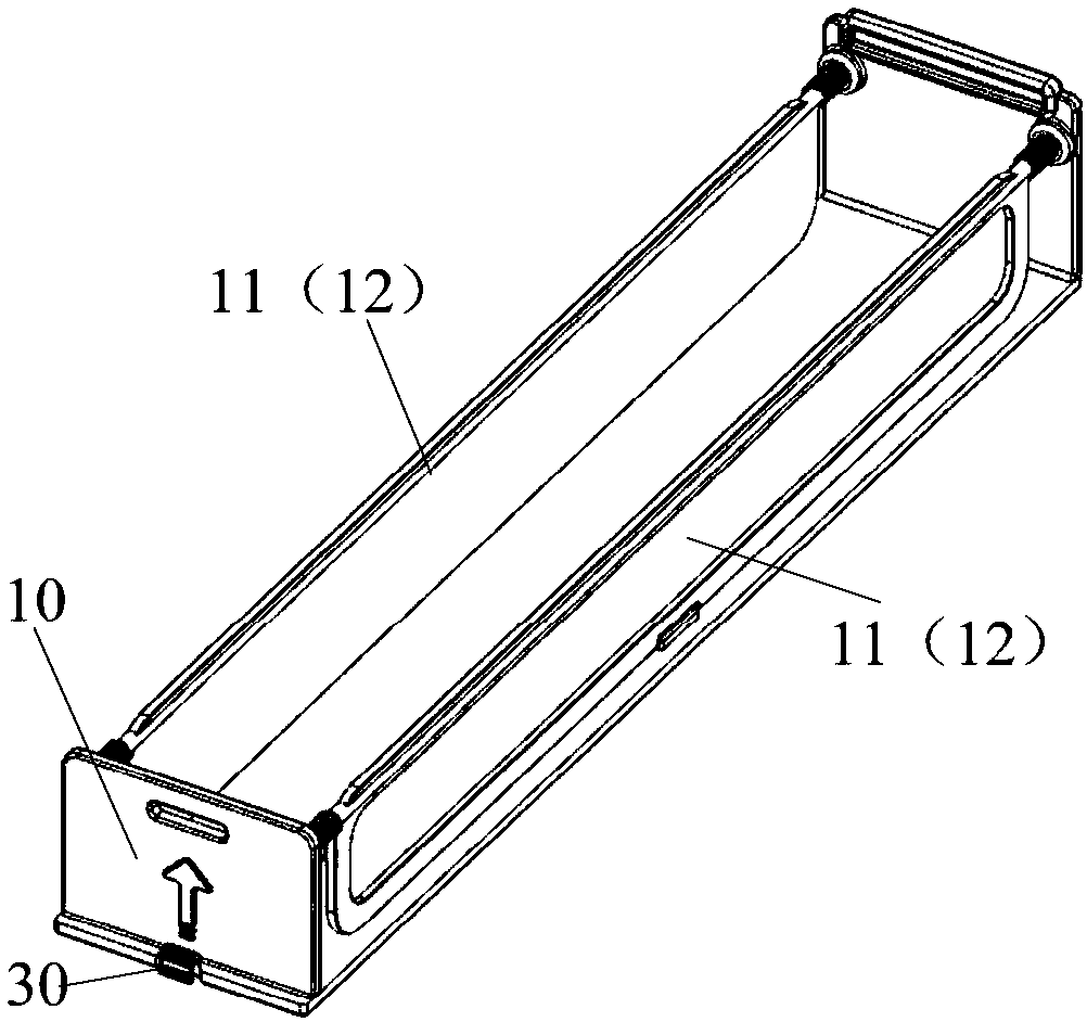
[0061] Such as Figure 5 with Image 6 As shown, the two baffles 11 are all arranged on the housing 10 and are respectively located inside the two water holes 13 (in the inner cavity of the hou...

Embodiment 3

[0068] Such as Figure 7-Figure 14As shown, in the third embodiment, the filter structure 12 is installed on the side of the casing 10 provided with the water hole 13, and the filter structure 12 can be a filter mesh. The two baffles 11 are all arranged on the housing 10 and are respectively located inside the two water holes 13 (in the inner cavity of the housing 10). The area of ​​the baffles 11 is larger than the area of ​​the water holes 13. When the water flows through Push the two baffles 11 in one direction, one of the baffles 11 swings toward the inner cavity, the water hole 13 on this side is opened, and the water flows into the inner cavity of the housing 10 through the water hole 13; The other side baffle 11 swings to the outside, and the side baffle 11 is in contact with the housing 10, then the side baffle 11 covers the water hole 13, and the water flows out through the filter structure 12 on the side.

[0069] The baffle 11 can be made of a rigid material or a f...


PUM


Abstract

The invention provides a filtering and lifting device and a roller washing machine, and relates to the technical field of household appliances. The problem that a roller washing machine is poor in washing effect in the prior art is solved. The filtering and lifting device comprises a shell with an inner cavity. The two opposite sides in the water flow passing direction of the shell are each provided with a water passing hole. A baffle is arranged beside each water passing hole. At least part of the area of the side face of each water passing hole and/or the corresponding baffle on the shell isprovided with a filtering structure. The baffles are pushed by water flow to swing toward the inner side of the shell so as to completely expose the water passing holes, and the baffles are pushed bywater flow to swing towards the outer side of the shell so as to cover the water passing holes, so water flows out of the inner cavity of the shell through the filtering structure. The filtering andlifting device is applied to the roller washing machine and used for filtering away hair and other sundries in an inner tub, and the washing effect of the roller washing machine is improved.

Description

technical field [0001] The invention relates to the technical field of household appliances, in particular to a filter lifting device and a drum washing machine. Background technique [0002] A washing machine is a common household appliance, and a drum washing machine is one of the washing machines. An outer cylinder and an inner cylinder are arranged in the drum washing machine, and lifting ribs are arranged in the inner cylinder. During the working process of the drum washing machine, the inner cylinder rotates relative to the outer cylinder, and the lifting ribs rotate with the inner cylinder. During the rotation of the lifting ribs, the clothes in the inner cylinder are driven to move upwards. After moving a certain distance, the clothes fall under the influence of gravity. Repeatedly to clean the clothes. [0003] At present, in the process of washing clothes in the washing machine, a large number of small impurities (such as dander, hair, paper scraps, cotton and lin...

Claims


Application Information

Patent Timeline
Patent Type & Authority Applications(China)
IPC IPC(8): D06F39/10
CPCD06F39/10
Inventor 颜磊
Owner SUZHOU SAMSUNG ELECTRONICS CO LTD
Why Eureka
Try Eureka