Oriented fixed-layer slurry-injecting sleeve valve tube and slurry-injecting method

A technology of sleeve valve pipe and grouting, which is applied in the field of geotechnical engineering grouting, can solve the problems of increasing geological environmental pollution, failure of grouting reinforcement, and increasing construction difficulty, so as to reduce unnecessary pollution, have strong practicability, reduce cost effect

Pending Publication Date: 2018-06-22
SHENYANG JIANZHU UNIVERSITY
View PDF6 Cites 0 Cited by
  • Summary
  • Abstract
  • Description
  • Claims
  • Application Information

AI Technical Summary

Problems solved by technology

[0003] Most of the existing sleeve valve pipes use the method of pressure spraying grout to carry out grouting reinforcement in all directions of all soil layers within the drilling depth range, and it is impossible to accurately carry out specific direction grouting on the soil layer at the specified depth and within a certain thickness range. grouting reinforcement
For some projects that only need to be reinforced by grouting in a specific direction and depth position, and within a specified thickness range, if the sleeve valve pipe is used for construction, on the one hand, the construction difficulty will be increased, and on the other hand, the raw material will be damaged. waste of
At the same time, due to the additional grouting of the land that does not need to be reinforced, the pollution to the geological environment has increased

Method used


Image

  • Oriented fixed-layer slurry-injecting sleeve valve tube and slurry-injecting method
  • Oriented fixed-layer slurry-injecting sleeve valve tube and slurry-injecting method
  • Oriented fixed-layer slurry-injecting sleeve valve tube and slurry-injecting method

Examples


Embodiment Construction

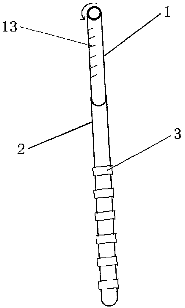
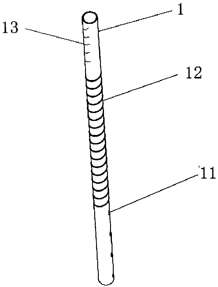
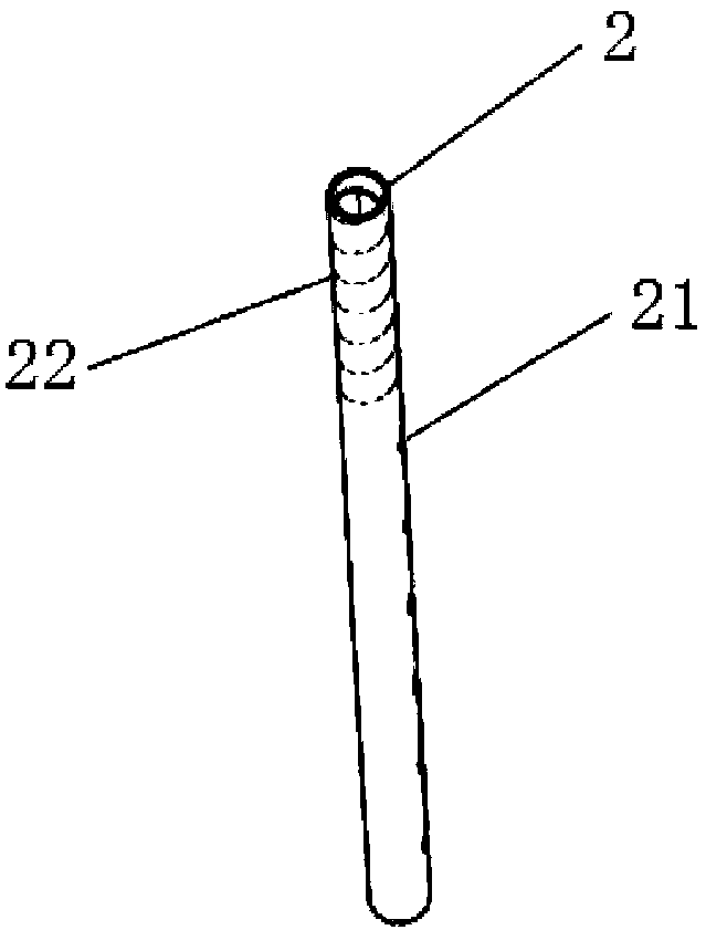
[0020] Such as Figures 1 to 3 As shown, a directional and layered grouting sleeve valve tube of the present invention includes an inner tube 1 , an outer tube 2 and a plurality of rubber rings 3 . A number of slurry outlet holes 21 with the same diameter are arranged at equal intervals from bottom to top on one side of the outer tube 2 , and an internal thread 22 is provided above the topmost slurry outlet hole 21 of the outer tube 2 . The inner pipe 1 is embedded in the outer pipe 2, and a plurality of grouting holes 11 with the same aperture are arranged at equal intervals on one side of its lower end, and above the topmost grouting hole 11 of the inner pipe 1, there is a groove corresponding to the inner thread 22. With the matched external thread 12, the bottom end face of the inner pipe 1 is closed. The rubber ring 3 is sleeved on the outer tube 2 and sealed on the pulp outlet 21 , and a small hole is opened on the rubber ring 3 corresponding to the pulp outlet 21 . Th...


PUM


Abstract

The invention discloses an oriented fixed-layer slurry-injecting sleeve valve tube and a slurry-injecting method. The sleeve valve tube comprises an inner tube, an outer tube and a plurality of rubberrings, wherein a plurality of slurry outlet holes which are of the same hole diameters are distributed from bottom to top at one side of the outer tube at equal distance; inner threads are arranged at the upper end of the slurry outlet hole at the topmost end of the outer tube; the inner tube is embedded into the outer tube, and a plurality of slurry-injecting holes which are of the same hole diameter are formed in one side of the lower end of the inner tube at equal distance; outer threads which are matched with the inner threads are arranged at the upper end of the slurry-injecting hole atthe topmost end of the inner tube; the bottom end surface of the inner tube is sealed; the rubber rings sleeve the outer tube and seal the slurry outlet holes; and small holes are formed in positions,which correspond to the slurry outlet holes, of the rubber rings. Threads which are matched with one another are arranged between inner and outer tubes, and the inner tube can rotate in the outer tube and can move up and down, so that oriented fixed-soil-layer slurry injecting is realized.

Description

technical field [0001] The invention belongs to the technical field of geotechnical engineering grouting, and in particular relates to a directional and layer-fixed grouting sleeve valve pipe and a grouting method. Background technique [0002] The French Soletanche foundation engineering company invented the Soletanche repair method in the 1950s, which is a relatively advanced grouting construction technology. China has carried out a series of research and development on it after its introduction, and called it the sleeve valve pipe grouting method. Because the sleeve valve pipe grouting method can carry out fixed depth, quantitative, fixed degree, fixed section, intermittent and repeated grouting, it combines the advantages of compaction grouting, penetration grouting and splitting grouting, and is now widely used in China. outside civil engineering. [0003] Most of the existing sleeve valve pipes use the method of pressure spraying grout to carry out grouting reinforce...

Claims


Application Information

Patent Timeline
Patent Type & Authority Applications(China)
IPC IPC(8): E02D15/02
CPCE02D15/02E02D2250/003
Inventor 郭超陆征然于红梅张茂胜
Owner SHENYANG JIANZHU UNIVERSITY
Why Eureka
Try Eureka