Drilling rod connector with inner spraying and drilling fluid leaking preventing function

A drill pipe joint and ball head technology, which is applied to drill pipes, drilling equipment, drill pipes, etc., can solve the problems of short service life, loss of drilling fluid, and great harm, and achieve convenient operation, prevent leakage of drilling fluid, and avoid internal problems. spray dangerous effects

Pending Publication Date: 2018-06-22
NORTHEAST GASOLINEEUM UNIV
View PDF0 Cites 2 Cited by
  • Summary
  • Abstract
  • Description
  • Claims
  • Application Information

AI Technical Summary

Problems solved by technology

The current drilling technology has been able to control the external spraying well, but the internal spraying of the drill pipe is more harmful and has not been effectively solved; and in the process of deep well drilling, it is necessary to repeatedly connect a single piece, and the process of unloading the drill pipe will cause a lot of damage. Drilling fluid leakage poses a threat to the safety of drilling platform operations and makes the working environment of operators worse
Although the anti-splash joint design was proposed in the 1990s, its structure has disadvantages such as short service life, sealing delay, and frequent sealing failures. Some scholars have proposed an innovative design for the old structure, adding a spring structure to Avoid frequent sealing problems, but because the spring structure is in direct contact with the drilling fluid, it is easy to cause erosion and corrosion of the spring, resulting in automatic sealing failure and other problems, which cannot meet the requirements of drilling work

Method used


Image

  • Drilling rod connector with inner spraying and drilling fluid leaking preventing function
  • Drilling rod connector with inner spraying and drilling fluid leaking preventing function
  • Drilling rod connector with inner spraying and drilling fluid leaking preventing function

Examples


Embodiment Construction

[0049] The present invention will be further described below in conjunction with accompanying drawing:

[0050] The present invention can achieve the following purposes: when drilling into a high-pressure formation during drilling, the blowout prevention structure design of the special joint can quickly and automatically close the overflow area to prevent the drilling fluid from blowing out; when the drilling platform is connected to a single , the pump pressure is reduced to zero, and the annular flow channel is automatically closed through the automatic reset function of the sealing structure, and the upper hydrostatic pressure is offset by the spring preload, so as to prevent the loss of drilling fluid when a single connection is made. It fills up the domestic gap in the design of the drill pipe structure for preventing the drilling fluid from blowing out during the drilling process.

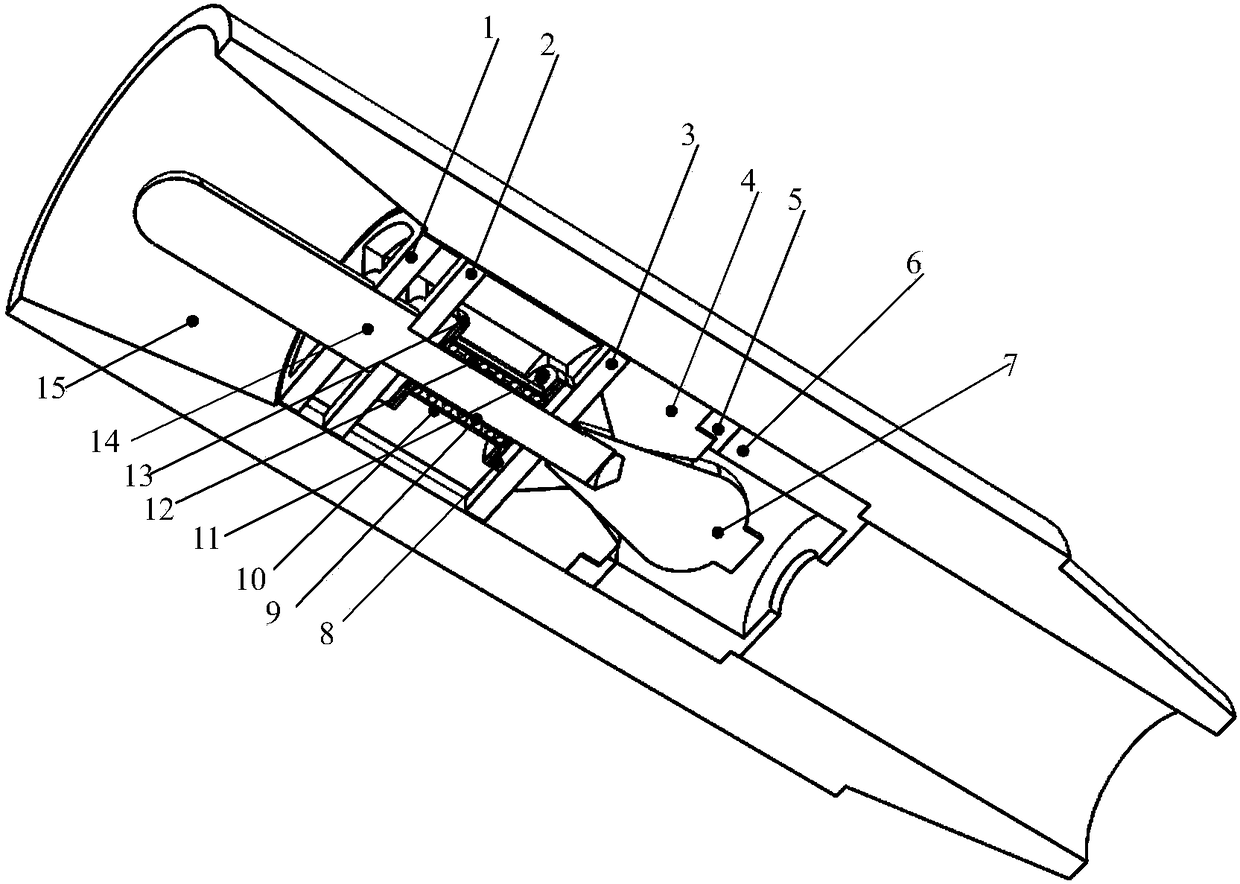
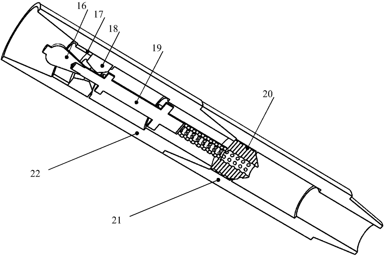
[0051] Such as figure 1 to combine figure 2 As shown, the main seal structure of the ...


PUM


Abstract

The invention provides a drilling rod connector with an inner spraying and drilling fluid leaking preventing function and mainly aims to provide a drilling rod structure capable of preventing inner spraying of drilling fluid in drilling of an oil field drilling platform and leaking of a great quantity of drilling fluid in splicing of single rods. The drilling rod connector is characterized in thatthe drilling rod connector comprises a main sealing structure and an auxiliary sealing structure, the main sealing structure comprises a fixed cross-shaped partition ring, a movable cross-shaped partition ring, a limiting ring, a center cross-shaped pipe, a sealing rubber ring, a linkage ball limiting ring, a sealing linkage ball, a spring device base, an inner sealing rubber cylinder, an outer sealing rubber cylinder, a fixing bolt, a spring, a spring device outer sealing shell, a linkage ball connecting rod and an upper drilling rod connector, and the auxiliary sealing structure comprises an auxiliary sealing linkage ball, a lower sealing rubber ring, an auxiliary linkage ball sealing seat, an auxiliary linkage ball connecting rod, a filtering element, a lower drilling rod connector anda middle drilling rod connector. The main sealing structure and the auxiliary sealing structure are combined through the upper drilling rod connector and the middle drilling rod connector which are screwed as well as the middle drilling rod connector and the lower drilling rod connector which are screwed.

Description

technical field [0001] The invention relates to a drill pipe structure which is used to prevent drilling fluid from spraying inside when drilling on an oil field drilling platform and to prevent a large amount of drilling fluid from leaking when a single piece is connected. Background technique [0002] Oilfield development has entered the stage of remaining oil exploitation, and oil and gas exploitation has gradually entered the high-temperature and high-pressure intervals. Drilling is the first step in oil and gas extraction. Under the current environment, the drill pipe will inevitably drill into the high-temperature and high-pressure formation in the final stage of new well drilling. The instantaneous pressure rise of the formation will pose a great challenge to the blowout prevention control technology of the drill pipe. . The current drilling technology has been able to control the external spraying well, but the internal spraying of the drill pipe is more harmful and...

Claims


Application Information

Patent Timeline
IPC IPC(8): E21B17/04E21B21/10
CPCE21B17/04E21B21/10
Inventor 李森曹梦雨王尊策闫月娟徐艳张井龙
Owner NORTHEAST GASOLINEEUM UNIV
Why Eureka
Try Eureka