A sliding vane compressor whose cylinder rotates with the rotor

A compressor and sliding vane technology, applied in the field of compressors, can solve the problems of unbalanced quality of crankshaft affecting smooth operation, large mechanical friction between the sliding vane and rotor cylinder, complicated structure of screw compressors, etc., so as to achieve convenient clearance adjustment and control. , The structure and support method are simplified, and the force is uniform.

Active Publication Date: 2019-06-21
SOUTHEAST UNIV
View PDF5 Cites 0 Cited by
  • Summary
  • Abstract
  • Description
  • Claims
  • Application Information

AI Technical Summary

Problems solved by technology

[0002] Since the piston compressor is a reciprocating type, the unbalanced quality of the crankshaft affects its smooth operation and makes a lot of noise
The structure of the screw compressor is relatively complicated, so it cannot be used in micro occasions, and can only be used in the medium and low pressure range
The sliding vane compressor has simple structure, easy manufacture, convenient operation and maintenance, almost no vibration and axial force, but its main disadvantage is that there is a large mechanical friction between the sliding vane and the rotor cylinder, resulting in a large energy loss , so its efficiency is more than 10% lower than that of screw and reciprocating compressors

Method used


Image

  • A sliding vane compressor whose cylinder rotates with the rotor
  • A sliding vane compressor whose cylinder rotates with the rotor
  • A sliding vane compressor whose cylinder rotates with the rotor

Examples


Embodiment Construction

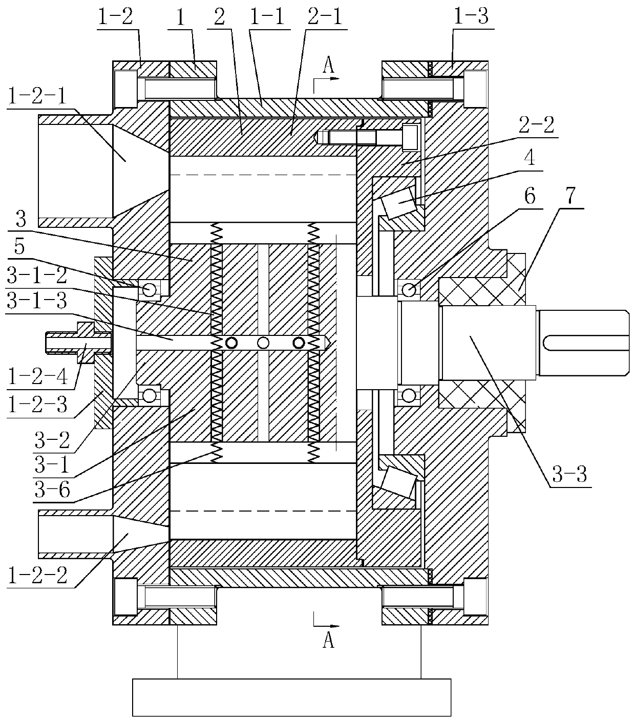
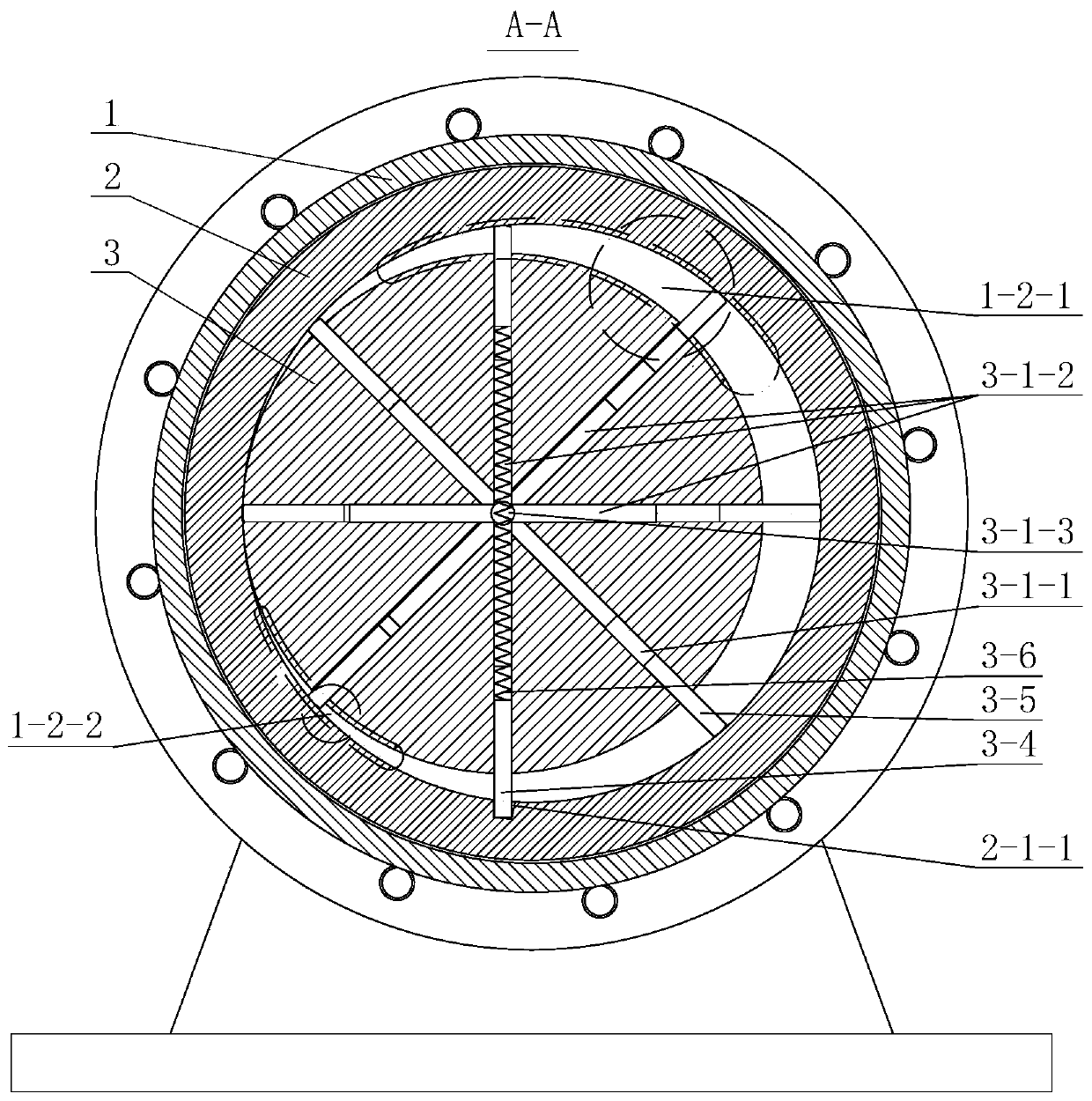
[0013] A sliding vane compressor in which the cylinder rotates with the rotor, comprising a cylindrical casing 1 with a base, a moving cylinder 2 is arranged inside the cylindrical casing 1 and the cylindrical casing 1 and the moving cylinder 2 are arranged coaxially, and the A rotor 3 is provided in the moving cylinder 2 and the moving cylinder and the rotor 3 are arranged eccentrically. An air inlet 1-2-1 and an air outlet 1-2-2 are arranged on the left end surface of the casing, and the inlet The air port 1-2-1 is located in the crescent-shaped gap area between the moving cylinder and the rotor, along the rotor rotation direction from small to large, and the air outlet 1-2-2 is located in the crescent-shaped gap between the moving cylinder and the rotor The position from large to small along the direction of rotation of the rotor in the area; ≥8 even-numbered axial rectangular grooves 3-1-1 are evenly distributed on the rotor 3, and in each group of opposite rectangular groo...


PUM


Abstract

The invention discloses a sliding piece type compressor with a cylinder rotating with a rotor. The sliding piece type compressor with the cylinder rotating with the rotor includes a cylindrical machine shell, wherein a pneumatic cylinder is arranged in the cylindrical machine shell and is coaxial with the cylindrical machine shell. The rotor is arranged in the pneumatic cylinder and is arranged eccentrically with the pneumatic cylinder, and an air inlet and an air outlet are formed in the left end surface of the machine shell. The air inlet and the air outlet are correspondingly located in a position changed from being small to being big and a position change from being big to being small along the direction of the rotor rotation, the positions are located in crescent shaped clearance areas between the pneumatic cylinder and the rotor. More than eight even numbered axial rectangular grooves are evenly formed in the rotor, and at least two radial through holes are formed in the rectangular grooves. A sliding piece is embedded in the rectangular grooves, and one wide sliding piece is embedded in the inner wall of the pneumatic cylinder. The rest of the sliding pieces abut against theinner wall of the pneumatic cylinder under the action of a compression spring. The compressor has the advantages of small friction loss and high efficiency because the pneumatic cylinder rotates along the compressor.

Description

technical field [0001] The invention relates to a compressor, in particular to a sliding vane compressor in which a cylinder rotates with a rotor. Background technique [0002] Since the piston compressor is a reciprocating type, the unbalanced quality of the crankshaft affects its smooth operation, and the noise is relatively large. The structure of the screw compressor is relatively complicated, and it cannot be used in micro occasions, and can only be used in the medium and low pressure range. The sliding vane compressor has simple structure, easy manufacture, convenient operation and maintenance, almost no vibration and axial force, but its main disadvantage is that there is a large mechanical friction between the sliding vane and the rotor cylinder, resulting in a large energy loss , so its efficiency is more than 10% lower than that of screw and reciprocating compressors. Contents of the invention [0003] The invention provides a sliding vane compressor in which a...

Claims


Application Information

Patent Timeline
Patent Type & Authority Patents(China)
IPC IPC(8): F04C18/344F04C29/00F04C29/12
CPCF04C18/3441F04C29/00F04C29/12F04C2240/10F04C2240/20F04C2240/30
Inventor 陈亚平周晓裕吴嘉峰顾花朵
Owner SOUTHEAST UNIV
Why Eureka
Try Eureka