Speed ​​table brake device

A braking device and vehicle speed technology, applied in the field of vehicle detection, can solve problems such as poor braking effect, achieve the effect of improving braking effect, reducing the frequency of equipment replacement, and improving the meshing degree

Active Publication Date: 2019-07-23
郎溪品旭科技发展有限公司
View PDF8 Cites 0 Cited by
  • Summary
  • Abstract
  • Description
  • Claims
  • Application Information

AI Technical Summary

Problems solved by technology

[0005] The present invention intends to provide a vehicle speed table braking device to solve the problem of poor braking effect in the prior art

Method used


Image

  • Speed ​​table brake device
  • Speed ​​table brake device
  • Speed ​​table brake device

Examples


Embodiment Construction

[0024] The following is further described in detail through specific implementation methods:

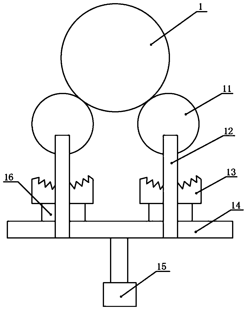
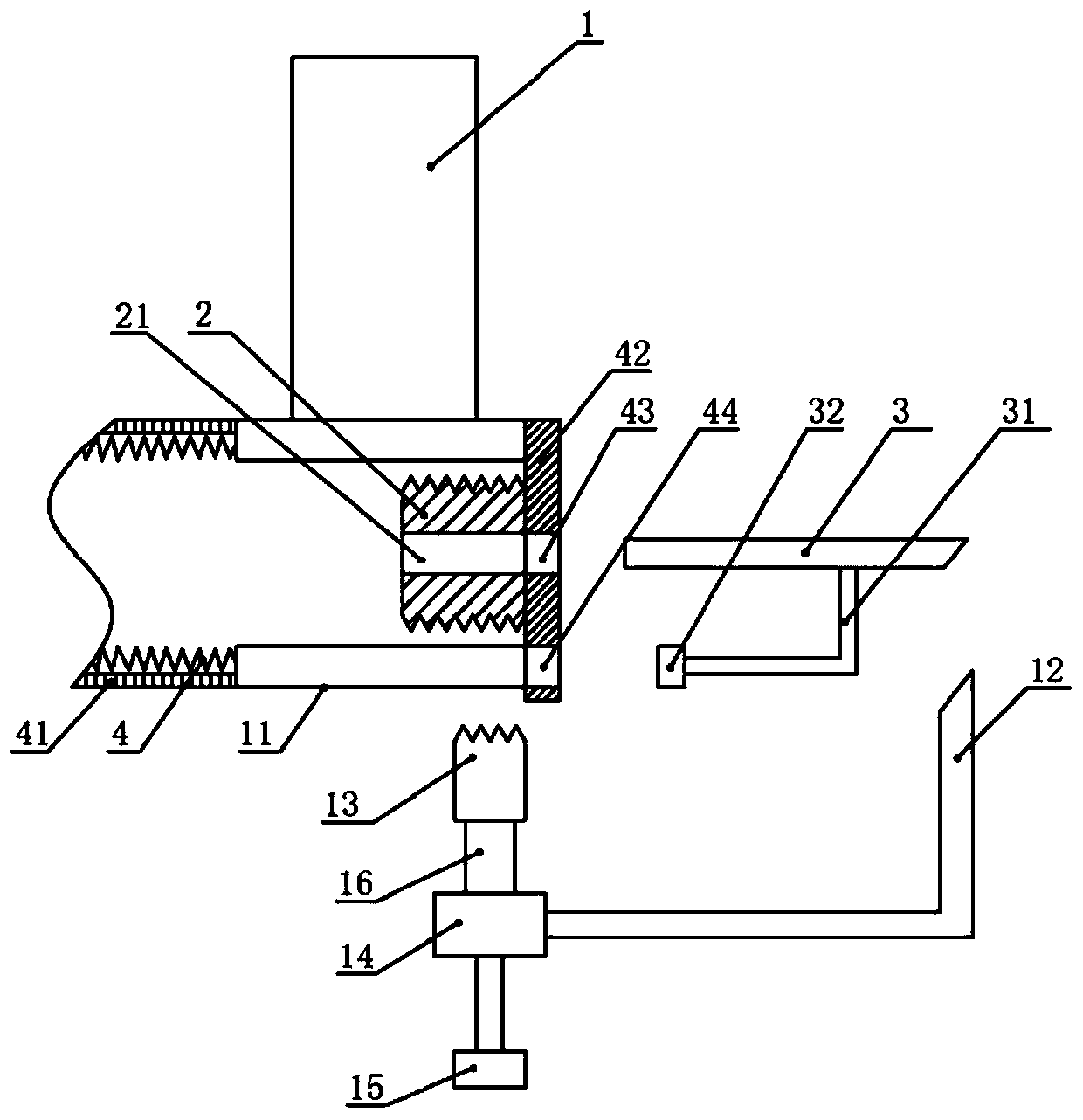
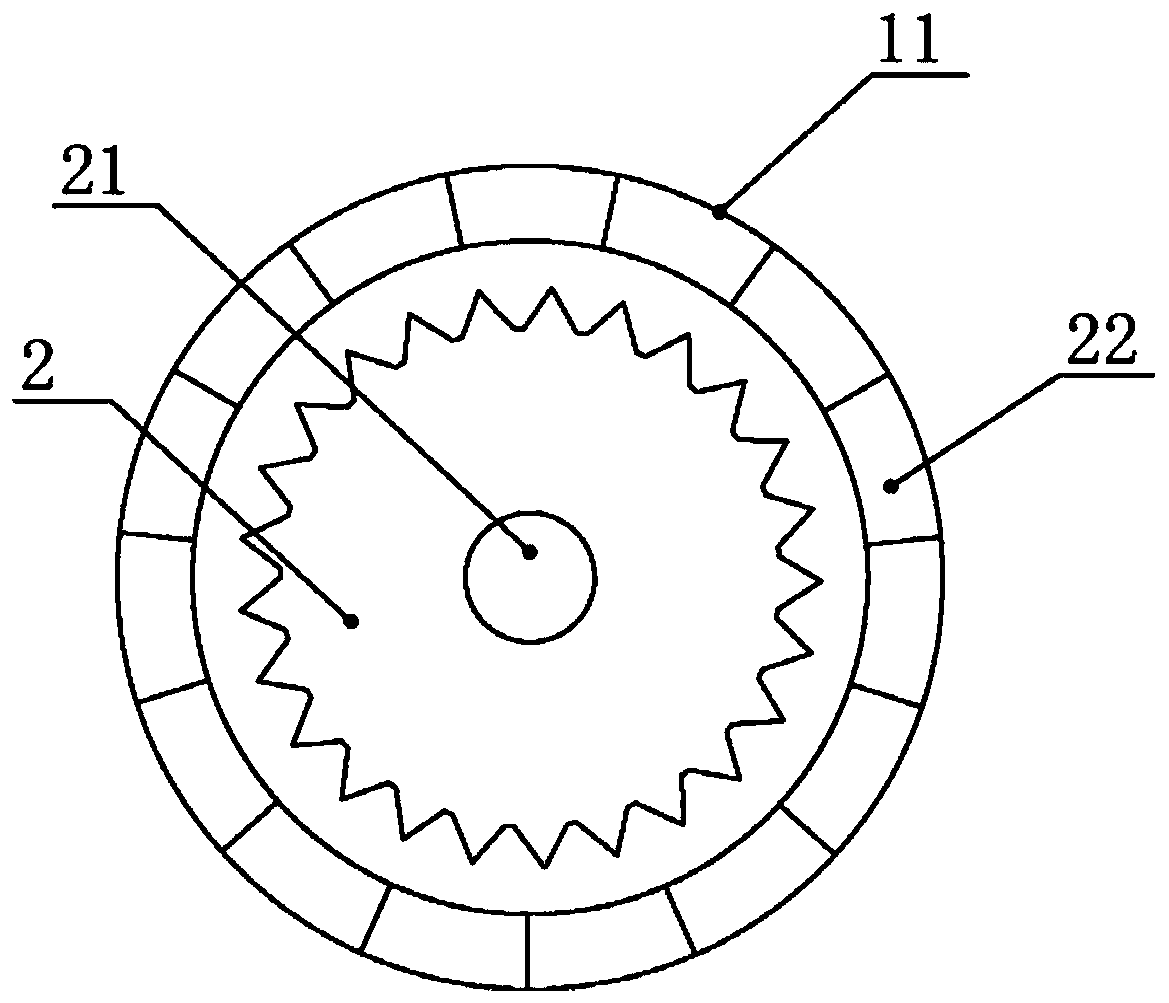
[0025] The reference signs in the accompanying drawings of the specification include: wheel 1, roller 11, wedge rod 12, tooth plate 13, support frame 14, cylinder 15, connecting frame 16, ring gear 2, through hole 21, slide plate 22, push rod 3, Connecting rod 31, push plate 32, spring 4, telescopic plate 41, cover plate 42, second through hole 43, arc-shaped hole 44.

[0026] Such as figure 1 As shown, the brake device of the vehicle speed table of the present invention includes a support frame 14, a cylinder 15 is connected to the bottom of the support frame 14, and a tooth plate 13 is installed above the support frame 14. The cross section of the tooth plate 13 is arc-shaped, and the tooth plate 13 is connected through the The frame 16 is detachably connected with the support frame 14, which is convenient for removing the tooth plate 13 for repair and maintenance.

[0027] Such ...


PUM


Abstract

The invention relates to the technical field of vehicle detection, in particular to a speedometer test bench braking device, comprising a support frame. A driving mechanism is connected to the bottomof the support frame; a toothed plate is arranged on the support frame, a roller is arranged above the toothed plate, a toothed ring is concentrically arranged in the roller, the idle of the toothed ring is provided with a first through hole, the roller is formed by enclosing a plurality of slide plates, one end of the roller is provided with a retaining plate, a spring is connected between the retaining plate and each slide plate, a wedged rod is perpendicularly connected to one side of the support frame, a push rod is arranged above the wedged rod, one end of the push rod is provided with awedged face matching with the wedged rod, a push plate is arranged below the push rod, the push plate is in arc shape matching with the roller, each side of the push rod is connected with an L-shapedconnection rod, the other ends of the connection rods are connected with the two ends of the push plate respectively. The problem that the prior art has poor braking effect is solved.

Description

technical field [0001] The invention relates to the technical field of vehicle detection, in particular to a braking device for a vehicle speed table. Background technique [0002] The vehicle speed table, also known as the vehicle speed detection table, is a special equipment for detecting the speed of the vehicle. Generally, it includes two free rollers. When the vehicle speed is detected, the rotation of the wheels drives the two free rollers of the speedometer to rotate, and the vehicle speed can be measured by detecting the speed of the free rollers. After the detection is completed, the free roller stops rotating, and the vehicle leaves the speed table. When the vehicle leaves, it is necessary to brake the free roller to prevent the free roller from rotating together with the wheels, so that the vehicle can leave the speedometer smoothly. [0003] In the prior art, a brake device is usually used to brake the free roller. This type of braking device uses two wear-res...

Claims


Application Information

Patent Timeline
Patent Type & Authority Patents(China)
IPC IPC(8): G01M17/007
CPCG01M17/007
Inventor 卢加权
Owner 郎溪品旭科技发展有限公司
Why Eureka
Try Eureka