
A kind of impeller for centrifugal pump with variable curvature

A technology of bending and centrifugal pumps, applied in the field of centrifugal pumps, can solve the problems of high cost, large number of impellers, and long replacement time of impellers

Active Publication Date: 2019-10-15
ANHUI YINLONG PUMP VALVE
View PDF5 Cites 0 Cited by
  • Summary
  • Abstract
  • Description
  • Claims
  • Application Information

AI Technical Summary

Problems solved by technology

The degree of curvature of the impeller blades of a centrifugal pump directly affects the head of the centrifugal pump, but the influence of the degree of blade curvature on the head of the centrifugal pump cannot be directly obtained through calculation. It takes a lot of manpower and material resources to conduct experiments on impellers with different degrees of curvature, and the cost is relatively high
[0003] In the teaching process, impellers with blades with different degrees of curvature are used for demonstration. When using less impellers, the degree of curvature of the blades is discontinuous, and it is impossible for students to intuitively understand the influence of the degree of curvature of the blades on the pump lift; while using more Demonstration of the impeller, the replacement of the impeller takes a long time, and the large number of impellers also makes the cost higher

Method used


Image

  • A kind of impeller for centrifugal pump with variable curvature
  • A kind of impeller for centrifugal pump with variable curvature
  • A kind of impeller for centrifugal pump with variable curvature

Examples


Embodiment Construction

[0017] The present invention will be further explained below in conjunction with the accompanying drawings and specific embodiments. It should be understood that the following specific embodiments are only used to illustrate the present invention and are not intended to limit the scope of the present invention. It should be noted that the words "front", "rear", "left", "right", "upper" and "lower" used in the following description refer to the directions in the drawings, and the words "inner" and "outer ” refer to directions towards or away from the geometric center of a particular part, respectively.

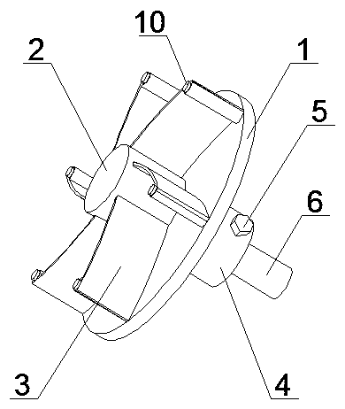
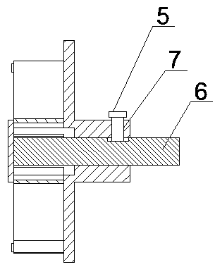
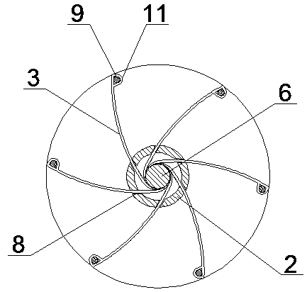
[0018] Such as figure 1 The shown impeller for a centrifugal pump with variable curvature includes an impeller disk 1, a blade chamber 2, blades 3, a rotating shaft 6 and an impeller shaft 4, the impeller disk 1 is a circular disk, and the impeller chamber 2 is provided with a circular disk At the center of one side, the impeller chamber 2 is a closed hollow cylinder, and the ...


PUM


Abstract

The invention discloses an impeller used for a centrifugal pump with a variable bending degree. A blade bending degree can be rapidly and conveniently adjusted, and the blade bending degree is continuously changed. Especially in actual teaching, the blade bending degree can be conveniently, rapidly and continuously adjusted so that a student can visually understand the relation of the blade bending degree and centrifugal pump lift.

Description

technical field [0001] The invention belongs to the technical field of centrifugal pumps, in particular to an impeller for centrifugal pumps with variable curvature. Background technique [0002] Centrifugal pumps work by using the rotation of the impeller to cause the water to undergo centrifugal motion. The rotating impeller drives the water in the pump casing to rotate at a high speed. The water undergoes centrifugal motion and is thrown to the outer edge of the impeller and passes through the flow channel of the volute pump casing. The pressure water line flowing into the water pump. The degree of curvature of the impeller blades of a centrifugal pump directly affects the head of the centrifugal pump, but the influence of the degree of blade curvature on the head of the centrifugal pump cannot be directly obtained through calculation. Experiments on impellers with different degrees of curvature require a lot of manpower and material resources, and the cost is relatively...

Claims


Application Information

Patent Timeline
Patent Type & Authority Patents(China)
IPC IPC(8): G09B25/02
Inventor 吴杰徐俊东孟金华王清龙汪云王文汇唐宗清
Owner ANHUI YINLONG PUMP VALVE
Learn More