A gun head device that is convenient for distance measurement and a method for controlling the height of the print head

A technology of print head and control system, applied in the field of electrofusion additive manufacturing, can solve the problems of influence distance, influence of workpiece performance, influence of workpiece performance, etc., to achieve the effect of improving accuracy and reducing damage

Active Publication Date: 2020-08-11
NANFANG ADDITIVE MFG TECH
View PDF9 Cites 0 Cited by
  • Summary
  • Abstract
  • Description
  • Claims
  • Application Information

AI Technical Summary

Problems solved by technology

[0003] Among them, when the workpiece is processed by the electrofusion forming method, the printing accuracy of the gun head must be strictly controlled, such as the height and temperature of the print head. If it cannot be accurately controlled, it will have a serious impact on the performance of the processed workpiece. It will affect the distance between the conductive tip of the print head and the surface of the workpiece. If the distance deviates from the normal range, the thickness of each layer of the workpiece will be uneven, which will seriously affect the performance of the workpiece
[0004] In the prior art, an infrared sensor is generally used to detect the distance between the conductive tip and the surface of the workpiece, that is, an infrared sensor is installed on the tip of the gun, and the infrared rays emitted by the infrared sensor are directed at the surface of the workpiece. When the infrared rays reach the surface of the workpiece, they will be reflected. In this way, the distance between the contact tip and the surface of the workpiece can be inferred. However, when using this method, the infrared rays will be affected by the brightness of the workpiece surface, resulting in large measurement errors, which cannot meet the accuracy requirements of additive manufacturing.

Method used


Image

  • A gun head device that is convenient for distance measurement and a method for controlling the height of the print head
  • A gun head device that is convenient for distance measurement and a method for controlling the height of the print head

Examples


Embodiment 1

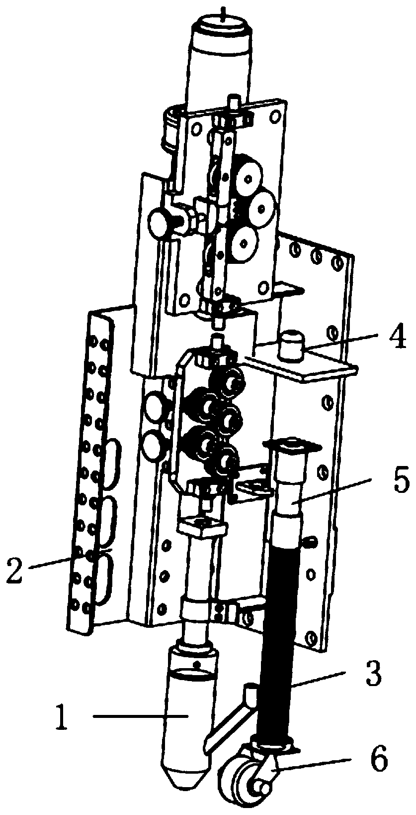
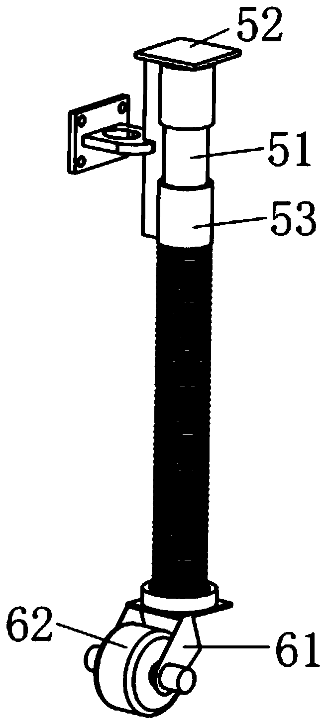
[0027] See attached figure 1 And attached figure 2 , the invention discloses a gun head device that is convenient for distance measurement, including a print head 1, a distance measurement mechanism, and a gun frame 2 for installing the print head 1 and the distance measurement mechanism. The distance detection assembly 4 on the 2 and the connecting rod group 5 installed under the distance detection assembly 4 can be lifted and lowered. The lower end of the connecting rod group 5 is equipped with a caster 6 relatively fixed in the axial direction, and the caster 6 is connected with the workpiece to be measured. The surface is always in a tight state. Wherein, the distance detecting component 4 is preferably an infrared distance measuring sensor. The present invention can also use other distance detection sensors, such as radar ranging sensors and the like. Wherein, the caster 6 is always in close contact with the surface of the workpiece to be measured through the downward...

Embodiment 2

[0038] The difference between this embodiment and Embodiment 1 is that the connecting rod group in this embodiment is guided by slide rails. Specifically, when the return elastic member is a return spring, the return spring exerts a force on the connecting rod assembly or the caster. Under the spring force, so that the casters and the surface of the workpiece to be measured are close. In order to improve the stability of the lifting of the connecting rod group, the gun head mechanism of this embodiment also includes a slide rail fixedly installed on the gun rack, the connecting rod group can be lifted and mounted on the sliding rail, and the return spring is sleeved on the sliding rail. outside the rail and above the connecting rod set.

Embodiment 3

[0040] This embodiment discloses a method for controlling the height of the print head described in Embodiment 1 and Embodiment 2, which includes the following steps:

[0041] A. The control system sets the preset distance L1 between the print head and the surface of the workpiece according to the process requirements;

[0042] B. The distance detection component detects the distance L2 between it and the connecting rod group, and transmits the detection result to the control system;

[0043] C. The control system calculates the distance L3 between the print head and the surface of the workpiece according to the detection results of the distance detection component, and compares L3 with L1 to obtain the deviation. The control system adjusts the height of the print head according to this deviation.

[0044] Wherein, the control system is preferably a programmable logic controller (abbreviated as PLC).

[0045] The invention realizes the closed-loop control of the height of the...


PUM


Abstract

The invention discloses a gun head device for distance measurement, which includes a print head, a distance measurement mechanism, and a gun frame for installing the print head and the distance measurement mechanism. The distance measurement mechanism includes a distance detection device fixedly installed on the gun frame The component and the connecting rod group that can be lifted and installed below the distance detection component, the lower end of the connecting rod group is equipped with casters that are relatively fixed in the axial direction, and the casters are always in close contact with the surface of the workpiece to be measured; the distance The detection component is used to detect the distance between it and the connecting rod group, so as to obtain the distance between the printing head and the surface of the workpiece. The invention also discloses a method for controlling the height of the printing head. The gun head device of the invention can accurately measure the distance between the printing head and the surface of the workpiece.

Description

technical field [0001] The invention relates to the field of electrofusion additive manufacturing, in particular to a gun head device that is convenient for distance measurement and a method for controlling the height of the print head of the gun head device. Background technique [0002] In order to improve the performance of key components in the heavy equipment industry (such as nuclear power, pressure vessels, penetrations or voltage stabilizers in the petrochemical industry, etc.), an electrofusion forming method has been developed in the prior art. This electrofusion forming method passes According to the experimental research, the chemical and mechanical properties of the workpiece processed by this electrofusion forming method are good. [0003] Among them, when the workpiece is processed by the electrofusion forming method, the printing accuracy of the gun head must be strictly controlled, such as the height and temperature of the print head. If it cannot be accurat...

Claims


Application Information

Patent Timeline
Patent Type & Authority Patents(China)
IPC IPC(8): B22F3/105B33Y10/00B33Y30/00B33Y50/02
CPCB22F3/003B33Y10/00B33Y30/00B33Y50/02B22F10/00B22F12/90B22F10/25B22F12/53Y02P10/25
Inventor 张子华朱晓龙朱晓强李骏棋张展榆
Owner NANFANG ADDITIVE MFG TECH
Why Eureka
Try Eureka