Measuring arm with self-balance shaft

A measuring arm and self-balancing technology, which is applied in the direction of measuring devices and instruments, can solve the problems of increasing the overall volume and weight of the balance shaft, the large horizontal length of the balance shaft of the measuring arm, large labor and time costs, etc., to reduce the volume and weight, ensure the consistency of accuracy, and reduce the difficulty of installation

Pending Publication Date: 2018-06-26
GUANGZHOU ACCUGLEN INTELLIGENT TECH LTD
View PDF6 Cites 0 Cited by
  • Summary
  • Abstract
  • Description
  • Claims
  • Application Information

AI Technical Summary

Problems solved by technology

Since the balance shaft adopts a horizontal series installation method to arrange the self-balancing device, bearing mechanism and angle encoder, this results in a large horizontal length of the balance shaft of the measuring arm, which increases the overall volume and weight of the balance shaft, and is also not conducive to the measuring arm when rotating the measurement. stability of one's own position
At the same time, since the balance torsion spring needs to be installed accurately during the installation process to ensure the torque balance between the rotating shaft and the fixed shaft at any position, in the traditional measuring arm solution, the position of the slot holding the balance torsion spring is fixed, only The balance torsion spring can be adjusted by adjusting the oblique stop, and the rotating shaft and the fixed shaft are relatively closed structures, which makes the installation very difficult. It needs to be disassembled in a continuous cycle, adjust the position of the oblique stop, and then install and test. Find a suitable installation position of the balance torsion spring, which also causes huge labor and time costs

Method used


Image

  • Measuring arm with self-balance shaft
  • Measuring arm with self-balance shaft
  • Measuring arm with self-balance shaft

Examples


Embodiment 1

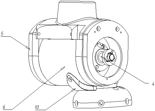
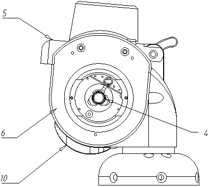
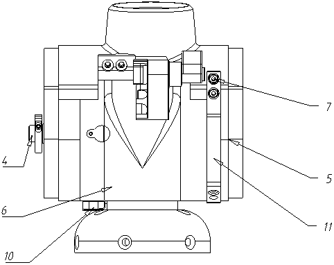
[0031] Such as Figure 1-5 The shown measuring arm with a self-balancing shaft includes: a fixed shaft 6, the fixed shaft 6 is a hollow structure, and the rear end surface of the fixed shaft 6 is provided with an axial fixed shaft annular groove 61;

[0032] The rotating sleeve 5, the rotating sleeve 5 includes a rotating side cover 51 corresponding to the rear end surface of the fixed shaft 6 and an upper cover arc plate 52 axially parallel to the fixed shaft 6; the inner surface of the rotating side cover 51 is provided There is a groove 53 in the rotating sleeve, and the groove 53 in the rotating sleeve corresponds to the annular groove 61 of the fixed shaft;

[0033] A connecting shaft 4, the connecting shaft 4 is rotationally connected with the fixed shaft 6 through the bearing mechanism 2, and one end of the connecting shaft 4 is connected with the rotating side cover 51;

[0034] A balance torsion spring 8, the balance torsion spring 8 is arranged in the annular groove...

Embodiment 2

[0038] Such as Figure 1-9 The shown measuring arm with a self-balancing shaft includes: a fixed shaft 6, the fixed shaft 6 is a hollow structure, and the rear end surface of the fixed shaft 6 is provided with an axial fixed shaft annular groove 61;

[0039] The rotating sleeve 5, the rotating sleeve 5 includes a rotating side cover 51 corresponding to the rear end surface of the fixed shaft 6 and an upper cover arc plate 52 axially parallel to the fixed shaft 6; the inner surface of the rotating side cover 51 is provided There is a groove 53 in the rotating sleeve, and the groove 53 in the rotating sleeve corresponds to the annular groove 61 of the fixed shaft;

[0040] A connecting shaft 4, the connecting shaft 4 is rotationally connected with the fixed shaft 6 through the bearing mechanism 2, and one end of the connecting shaft 4 is connected with the rotating side cover 51;

[0041] A balance torsion spring 8, the balance torsion spring 8 is arranged in the annular groove 6...


PUM


Abstract

The invention relates to a measuring arm with a self-balance shaft. The measuring arm comprises a fixed shaft, a rotary sleeve, a connecting shaft and a balance torsion spring, wherein the fixed shaftis of a hollow structure; an axial fixed shaft ring-shaped slot is formed in the rear side end surface of the fixed shaft; the rotary sleeve comprises a rotary side cover which corresponds to the rear side end surface of the fixed shaft and an upper cover arc-shaped plate axially parallel to the fixed shaft; a rotary sleeve concave slot is formed in the inner side surface of the rotary side cover; the rotary sleeve concave slot corresponds to the fixed shaft ring-shaped slot; the connecting shaft is rotatably connected with the fixed shaft through a bearing; one end part of the connecting shaft is connected with the rotary side cover; the balance torsion spring is arranged in the fixed shaft ring-shaped slot; one end part of the balance torsion spring is fixedly mounted in the rotary sleeve concave slot; and the other end part of the balance torsion spring is connected with the fixed shaft ring-shaped slot. The measuring arm can realize automatic torque balance to achieve the effectsof stabilizing gravity center, reducing size and weight, and reducing mounting difficulty of the balance torsion spring.

Description

technical field [0001] The invention relates to the field of self-balancing control of a measuring arm, in particular to a measuring arm with a self-balancing shaft. Background technique [0002] As a precision three-dimensional dimension measurement tool, the measuring arm is widely used in mold and part size and assembly inspection and measurement, such as reverse engineering, modeling design, digital-analog comparison and other applications. Its structure is composed of a base, multiple motion axes (usually 6-7) and a measuring head. It has the characteristics of small size, portable use, high precision, infinite rotation, and no dead point measurement. The structure of relative motion on the moving axis mainly includes two parts: the rotating axis and the fixed axis. When the measuring arm rotates and measures, except for the base and the first axis of motion (ie, the A axis), the position of the center of gravity of other parts changes correspondingly with the position...

Claims


Application Information

Patent Timeline
Patent Type & Authority Applications(China)
IPC IPC(8): G01B21/00
CPCG01B21/00
Inventor 艾鹰董俊阎素珍
Owner GUANGZHOU ACCUGLEN INTELLIGENT TECH LTD
Why Eureka
Try Eureka