
Photoelectric detector detection device and detection method

A technology of photoelectric detectors and detection devices, applied in measurement devices, instruments, etc., can solve the problems of occupying the time of detection personnel, low production efficiency of fiber optic gyroscopes, slow detection speed, etc., saving manpower and time, high degree of automation, The effect of reducing errors

Active Publication Date: 2018-06-26
HUNAN AEROSPACE ELECTROMECHANICAL EQUIP & SPECIAL MATERIAL INST
View PDF6 Cites 5 Cited by
  • Summary
  • Abstract
  • Description
  • Claims
  • Application Information

AI Technical Summary

Problems solved by technology

[0003] In order to improve the existing photodetector full-temperature test, the detection speed is slow, the time of the inspector is taken up, and the production efficiency of the fiber optic gyroscope is low, a photodetector detection device is proposed.

Method used


Image

  • Photoelectric detector detection device and detection method
  • Photoelectric detector detection device and detection method

Examples


Embodiment Construction

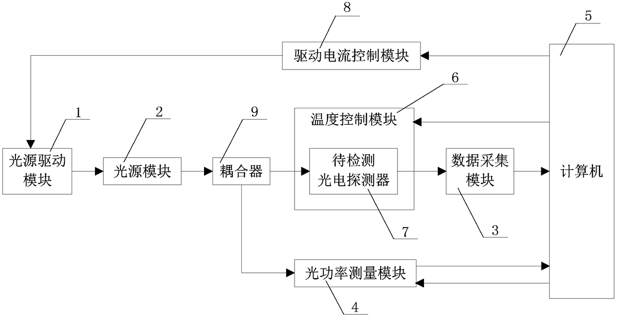
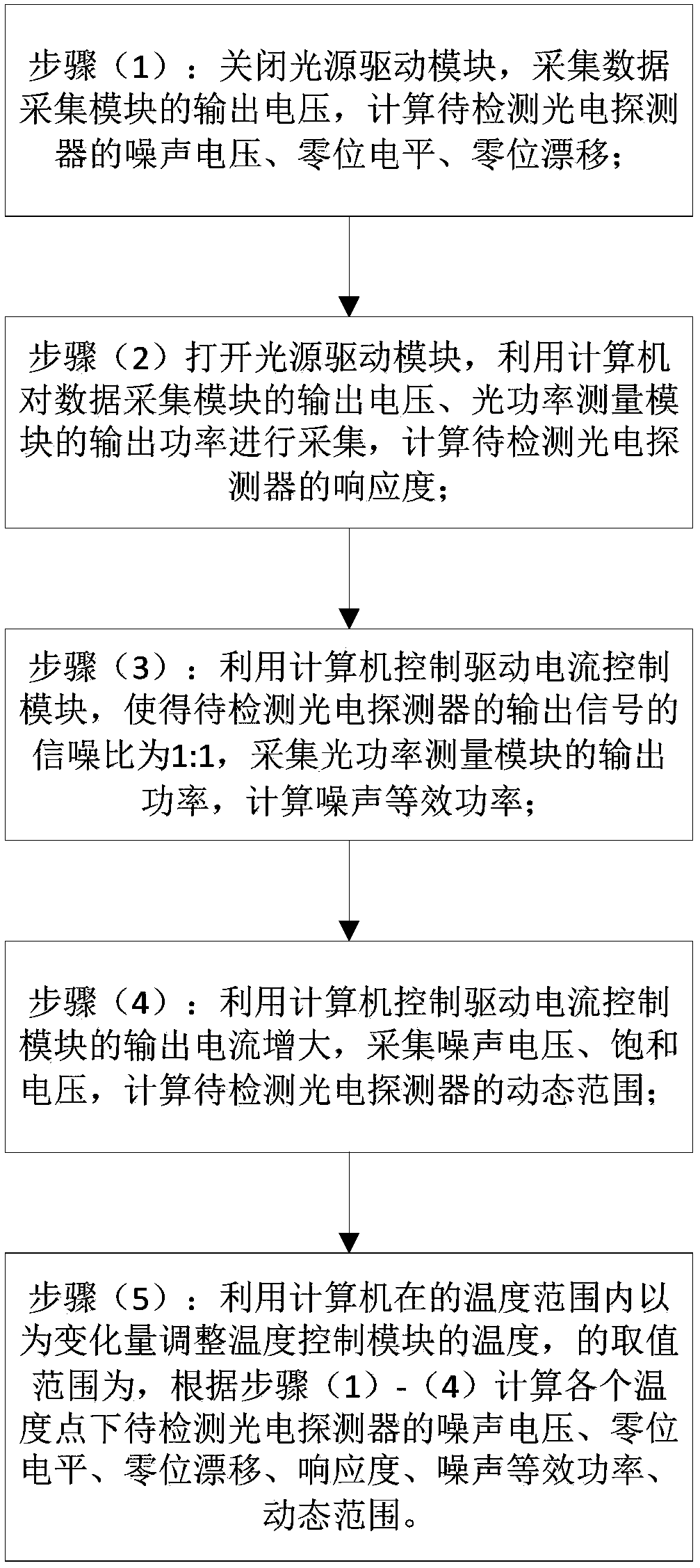
[0022] Refer below figure 1 , figure 2 The photodetector detection device of the present invention will be further described.

[0023] figure 1 It is a structural schematic diagram of the photodetector detection device of the present invention. The photodetector detection device includes a light source drive module 1, a light source module 2, a data acquisition module 3, an optical power measurement module 4, a computer 5, a temperature control module 6, a photodetector to be detected 7, a drive current control module 8, and a coupler 9 , the drive current control module 8, the light source drive module 1, the light source module 2, and the coupler 9 are sequentially connected, the photodetector 7 to be detected is connected to the data acquisition module 3, and the photodetector 7 to be detected is arranged in the temperature control module 6, one end output of the coupler 9 is connected with the photodetector 7 to be detected, and the other end output of the coupler 9 is...


PUM


Abstract

The invention provides a photoelectric detector detection device. The photoelectric detector detection device comprises a photoelectric detector to be detected, a data acquisition module, a computer,a driving circuit control module, a light source driving module, a light source module, and a coupler which are connected successively; and also comprises a temperature control module, and an opticalpowder measuring module which are connected with the computer; an output terminal of the coupler is connected with the photoelectric detector to be detected, and another output terminal of the coupleris connected with the optical powder measuring module; the photoelectric detector to be detected is arranged in the temperature control module. The invention also provides a photoelectric detector detection method. The photoelectric detector detection method can be used for measuring parameters such as the noise voltage, the zero level, the zero drift, the responsibility, the noise equivalent power, and the dynamic range. The photoelectric detector detection device and the detection method is capable of realizing photoelectric detector automatic detection, reducing artificial operation, saving manpower, shortening time, and especially increasing production efficiency and reducing error caused by artificial measuring in large batch detection.

Description

technical field [0001] The invention relates to a detection device and a detection method, in particular to a photoelectric detector detection device and a detection method, which belong to the field of optical fiber gyroscopes, and relate to a PC terminal control platform for optical fiber gyroscope photoelectric detector detection. Background technique [0002] The photodetector is the core component of the fiber optic gyroscope. The photodetector plays the role of converting optical signal into electrical signal and amplifying the electrical signal in the fiber optic gyroscope. With the application of fiber optic gyroscopes in civilian and military fields, the performance of photodetectors has also attracted much attention, and its working performance directly affects the performance and reliability of fiber optic gyroscopes. In the actual production process, the means and technology of full temperature detection of photoelectric detectors directly affect the production ...

Claims


Application Information

Patent Timeline
IPC IPC(8): G01C25/00
CPCG01C25/005
Inventor 张晓亮于中权
Owner HUNAN AEROSPACE ELECTROMECHANICAL EQUIP & SPECIAL MATERIAL INST
Learn More