Novel loose-item-free chip-type optical divider

An optical splitter and chip-type technology, which is applied in the field of new-type chip-free splitters without spare parts, can solve problems such as long production cycle, high cost, and signal transmission failure, so as to reduce the unit price of transportation and save raw materials , the effect of reducing product weight

CN108205176AActive Publication Date: 2018-06-26SICHUAN TIANYI COMHEART TELECOM
4 Cites 5 Cited by

Patent Information

Authority / Receiving Office
CN · China
Patent Type
Applications(China)
Current Assignee / Owner
Publication Date
2018-06-26

Smart Images

  • Figure 1
    Figure 1
  • Figure 2
    Figure 2
  • Figure 3
    Figure 3
Patent Text Reader

Abstract

The invention discloses an optical divider flange assembly with a rotary inner core and a casing in nested pair. Due to the fact that the inner core is rotatable and adjustable in the casing, the inlet direction of a ceramic ferrule can be adjusted according to the fiber introducing direction, so that bending and abrasion to the optical fiber at an inlet of the ceramic ferrule can be avoided, occupation of the space in a divider box by a fiber bundle can be reduced, long-term efficient use of the optical divider can be ensured, signal transmission failure caused by damage to the fiber can be avoided in the operation process, and the shortcomings of long production cycle and high cost caused by the fact that loose items must be purchased before production of the chip-type optical divider, and need to be threaded and assembled manually in the production process can be overcome.
Need to check novelty before this filing date? Find Prior Art

Description

technical field

[0001] The invention relates to an optical splitter, in particular to a novel insert-type optical splitter without spare parts. Background technique

[0002] In the plug-in optical splitters of the prior art, there is a miniature optical splitter, and the end of the miniature optical splitter needs to have a connector. When producing the connector, the front part of the connector must first be separated Parts (tail sleeve, stop ring, spring) are put on the optical fiber, and then put on the ceramic ferrule, and then all the rear parts (inner ferrule, outer ferrule) are assembled with the front parts, because each connector has It takes time, labor and materials to assemble, so the production cycle and cost constrain the development of optical communication. In addition, in the optical splitter, the optical fiber is usually separated by a bundle of optical fibers and then enters the ceramic ferrule. The optical fiber bundle is usually positioned at a certain ...

Examples

Embodiment Construction

[0018] The technical solution of the present invention will be further described in detail below in conjunction with the accompanying drawings, but the protection scope of the present invention is not limited to the following description.

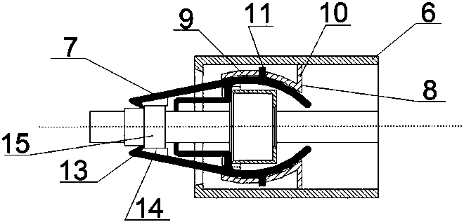
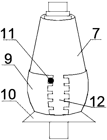
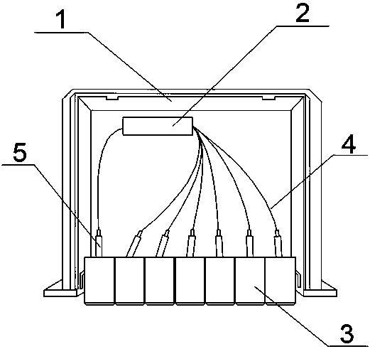
[0019] A new type of plug-in optical splitter without loose parts, including a plug-in bottom box 1, a miniature optical splitter 2, and a flange 3, the miniature optical splitter 2 is installed in the plug-in bottom box 1, The input end and the output end 4 of the miniature optical splitter 2 are penetrated into the ceramic ferrule 5 and fixed, and the ceramic ferrule 5 connected with the splitter is put into the end of the flange plate 3 without loose parts, and the flange plate 3 It includes an outer shell 6 and an inner core member 7 matched with the outer shell. A fixed mounting part 8 is embedded on the inner wall of the outer shell 6. The fixed mounting part 8 consists of a spherical shell-shaped rotating fixing part 9 and an outer sh...