Cable fall arrester

A fall arrester and cable technology, which is applied to cable laying equipment and other directions, can solve problems such as low construction efficiency, and achieve the effects of improving construction efficiency, low processing cost and convenient manufacturing.

Active Publication Date: 2020-01-21
CHINA NUCLEAR IND FIFTH CONSTR CO LTD
View PDF9 Cites 0 Cited by
  • Summary
  • Abstract
  • Description
  • Claims
  • Application Information

AI Technical Summary

Problems solved by technology

[0004] In order to solve the problem of low construction efficiency in the process of temporarily binding and fixing cables with ropes in the process of laying cables manually, the present invention proposes a cable fall arrester

Method used


Image

  • Cable fall arrester
  • Cable fall arrester
  • Cable fall arrester

Examples


Embodiment Construction

[0022] The technical solutions of the present invention will be described in detail below in conjunction with the accompanying drawings.

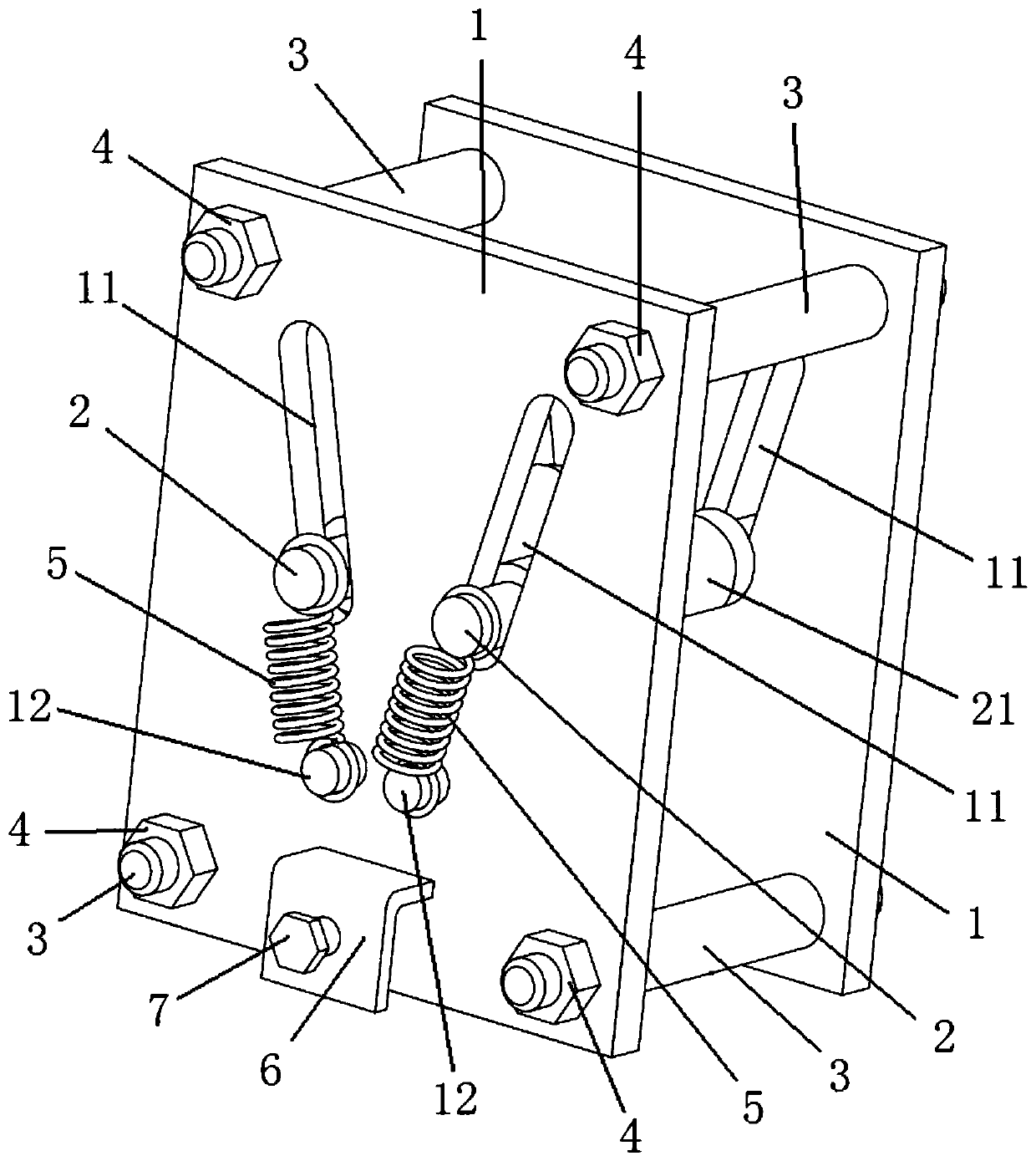
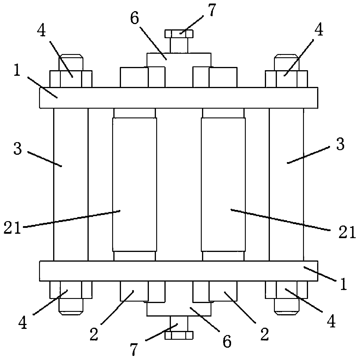
[0023] combine figure 1 with figure 2 As shown, the cable fall arrester of the present invention includes two support plates 1 and two fixing rods 2 . Wherein, two through chute 11 are provided on each support plate 1 , and the two chute 11 on the same support plate 1 are arranged in a V shape. The two support plates 1 are arranged in parallel, and the chute 11 on the two support plates 1 corresponds to each other, that is, the corresponding chute 11 communicates along the horizontal direction. The fixed rod 2 is located between the two support plates 1 , and the two ends of the fixed rod 2 are respectively passed through the corresponding slide grooves of the two support plates 1 . At this time, the two fixing rods 2 are parallel to each other, and can freely reciprocate and slide along the length direction of the chute 11 .

[0024] ...


PUM


Abstract

The invention belongs to the technical field of cable laying equipment, and specifically relates to a cable falling protection. The problem that the construction efficiency is low since the cable is temporarily bound and fixed by using a rope in the process of manually laying the cable is solved. The invention discloses a cable falling protector. The cable falling protector comprises two support plates and two fixed rods; two penetrating chutes are formed on each support plate, and two chutes on the same support plate are in V-shaped arrangement; two support plates are in parallel arrangement,and the chutes on two support plates are corresponding to each other; the fixed rod is located between two support plates, and two ends of the fixed rod respectively penetrate into the correspondingchutes of two support plates, and the fixed rod can freely reciprocate along the length direction of the chutes. The cable falling protector is not only simple in structure, convenient for manufacturing, operation and use, but also can quickly finish the clamping and fixation of the cable, and the construction efficiency is improved.

Description

technical field [0001] The invention belongs to the technical field of cable laying equipment, and in particular relates to a cable fall arrester. Background technique [0002] In the process of engineering construction, with the continuous increase in the use of electrical equipment, there are more and more cable laying tasks. At present, there are mainly two ways of laying cables, one is automatic or semi-automatic cable laying with equipment, such as a cable laying machine, and the other is manual laying, and the cable laying work is completed manually. Among them, in most cases, a large number of cables are laid with the help of cable laying machines, which can not only reduce the use of manpower and reduce labor costs, but also increase the speed of laying and improve construction efficiency. [0003] However, in some special working conditions, such as places with narrow spaces, it is still necessary to lay cables manually. At this time, although the number of cables...

Claims


Application Information

Patent Timeline
Patent Type & Authority Patents(China)
IPC IPC(8): H02G1/06
CPCH02G1/06
Inventor 耿川杨秋爽安庆乔长录杨永朋周丽萍
Owner CHINA NUCLEAR IND FIFTH CONSTR CO LTD
Why Eureka
Try Eureka