Ultra-high-speed switch type fault current limiting apparatus

A fault current-limiting, ultra-high-speed technology, applied in the field of high-voltage electrical equipment, can solve problems such as high reliability requirements, low safety reliability, arc operation, etc., to improve safety and stability, improve work reliability and service life , the effect of reducing the burden

Inactive Publication Date: 2018-06-26
成都智源电气有限责任公司
View PDF0 Cites 2 Cited by
  • Summary
  • Abstract
  • Description
  • Claims
  • Application Information

AI Technical Summary

Problems solved by technology

The series resonant fault current limiter and solid-state current limiter based on power electronic devices is a main direction of the current grid current limiting technology development, but the bypass of capacitors by such current limiters is realized by controlling power electronic devices such as thyristors. Therefore, the reliability requirements for such devices are high. Once the thyristor device fails, it will directly affect the current limiting effect
[0004] Superconducting fault current limiters are limited by the performance and price of superconducting materials, and have the disadvantages of high cost, high power consumption, large volume, and lack of large-scale application.
Although the fault current limiter based on fast mechanical switch has simple structure and low cost, it has the problem of arc operation, and its safety and reliability are relatively low.

Method used


Image

  • Ultra-high-speed switch type fault current limiting apparatus
  • Ultra-high-speed switch type fault current limiting apparatus

Examples


Embodiment Construction

[0028] The preferred embodiments of the present invention will be described in detail below in conjunction with the accompanying drawings, so that the advantages and features of the present invention can be more easily understood by those skilled in the art, so as to define the protection scope of the present invention more clearly.

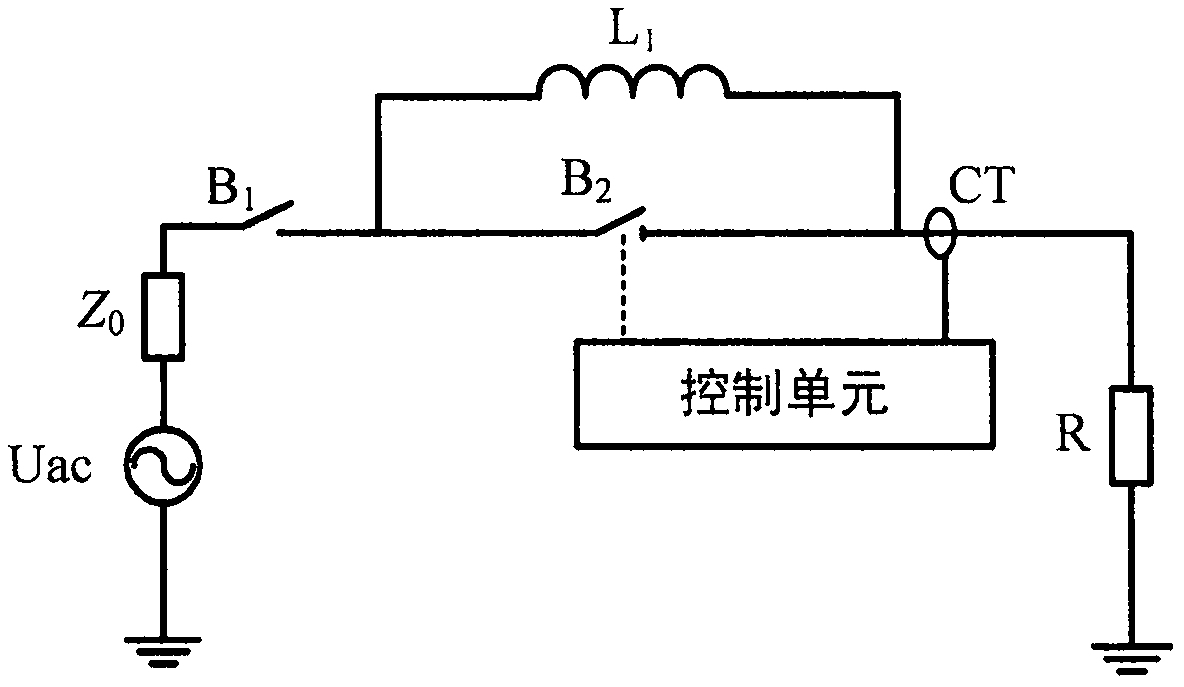
[0029] see figure 1 with figure 2 , the embodiment of the present invention includes:

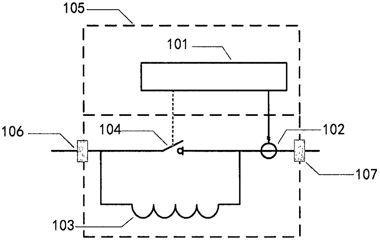
[0030] figure 1 It is an ultra-high-speed switch-type fault current limiting device of the present invention, such as figure 1 As shown, this embodiment includes: a main controller 101, a current transformer 102, a current-limiting reactor 103, an ultra-high-speed switch 104, an insulating cabinet 105, an incoming line terminal 106, and an outgoing line terminal 107;

[0031] The current-limiting reactor 103 is connected in parallel with the ultra-high-speed switch 104, and the incoming terminal 106 and the outgoing terminal 107 are connected in series on ...


PUM


Abstract

The invention provides an ultra-high-speed switch type fault current limiting apparatus. The ultra-high-speed switch type fault current limiting apparatus comprises a main controller, a current-limiting electric reactor, a magnetic control type ultra-high-speed switch, a current transformer, an insulating machine cabinet and a wire inlet / wire outlet terminal; the main controller controls on-off ofthe magnetic control type switch; the current-limiting electric reactor is connected with the magnetic control type ultra-high-speed switch in parallel to form a hybrid switch and then is connected with the wire inlet / wire outlet terminal in series; the current transformer detects a circuit current; the main controller is mounted on the upper part space of the insulating machine cabinet; and thewire inlet / wire outlet terminal adopts a ceramic type insulating protection sleeve; in normal operation, the current limiting apparatus is in zero resistance externally, and the magnetic control typeultra-high-speed switch is in a closed state; when the current transformer detects a faulty current, the main controller issues a control signal to disconnect the ultra-high-speed switch, and the current-limiting electric reactor is put into operation; and when the current transformer detects that the first large half wave of the current is zero crossing, the ultra-high-speed closing is separated,and the current-limiting electric reactor quits operation.

Description

technical field [0001] The invention relates to the field of high-voltage electrical equipment, in particular to an ultra-high-speed switch-type fault current limiting device. Background technique [0002] Once a short-circuit fault occurs in the traction power supply system, a huge short-circuit current will be generated, which will have an impact on the dynamic thermal stability of primary equipment such as transformer traction and insulators on the feeder line, seriously threatening the safe and reliable operation of the equipment. Due to its good operation stability and low impact on the system, the fault current limiter can reduce the burden of various electrical equipment such as circuit breakers to a certain extent, improve its working reliability and service life, and then improve the safety and stability of the traction power supply system It is an ideal device for fault current limiting of traction power supply system. [0003] In recent years, research on fault c...

Claims


Application Information

Patent Timeline
IPC IPC(8): H02H9/02H02H1/00
CPCH02H9/026H02H1/0007
Inventor 徐军郭春林
Owner 成都智源电气有限责任公司
Why Eureka
Try Eureka