Power device capable of resisting short-circuit fault and suppressing explosion

A power device and anti-short-circuit technology, which is applied in the direction of electrical components, circuit devices, emergency protection circuit devices, etc., can solve the problem of increasing the voltage overshoot and turn-off loss of active power devices, ignoring the short-circuit fault tolerance, which cannot be realized Short-circuit fault resistance and other issues, to achieve the effects of suppressing short-circuit fault current, optimizing short-circuit withstand capacity, and preventing device explosion

Active Publication Date: 2022-04-05
ZHEJIANG UNIV
View PDF5 Cites 0 Cited by
  • Summary
  • Abstract
  • Description
  • Claims
  • Application Information

AI Technical Summary

Problems solved by technology

[0010] To sum up, in the existing power device configuration, there is a trade-off relationship between "reducing voltage overshoot" and "improving short-circuit withstand capacity", while the current optimal design method only considers reducing the inductance of the commutation loop, Neglecting the degradation of its short-circuit fault withstand capability
At the same time, even if the dual AC power terminal design is adopted, it is only to improve the current carrying capacity of the AC power terminal of the power device
None of the above optimization design methods can achieve the function of resisting short-circuit faults and suppressing overcurrent explosion of power devices
In addition, in the scheme of preventing the explosion of the traditional power device configuration by connecting the fuse in series, since the fuse can only be connected to the DC power terminal, an additional inductance will be introduced in the commutation circuit, which further increases the active power device shutdown. Voltage overshoot and turn-off loss between collector and emitter during off-time

Method used


Image

  • Power device capable of resisting short-circuit fault and suppressing explosion
  • Power device capable of resisting short-circuit fault and suppressing explosion
  • Power device capable of resisting short-circuit fault and suppressing explosion

Examples


Embodiment Construction

[0057] In order to better understand the present invention, the technical solutions of the present invention will be clearly and detailedly described below in conjunction with the accompanying drawings and specific embodiments.

[0058] Aiming at the inability to realize the collaborative optimization of "commutation loop inductance" and "short-circuit withstand capacity" of power devices in the prior art, and relying only on the power device itself to suppress device explosion caused by over-current faults under short-circuit fault conditions, the present invention proposes A power device configuration design for short-circuit fault resistance and explosion suppression is proposed. The technical solutions of the embodiments of the present invention will be clearly and completely described below in conjunction with the accompanying drawings of the present invention.

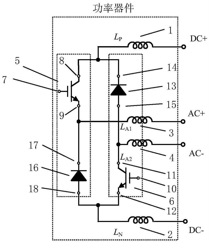
[0059] figure 1 Shown is a schematic diagram of the power device configuration design for short-circuit faul...


PUM


Abstract

The invention discloses a short-circuit-fault-resistant and explosion-suppression power device, and belongs to the technical field of power electronic devices. The power device comprises a direct current anode power terminal, a direct current cathode power terminal, two alternating current power terminals and a plurality of power semiconductor chips. The first commutation loop and the second commutation loop in the power device are decoupled in the device, so that a short-circuit fault current path comprises two alternating-current power terminals, the inductance of the short-circuit loop is increased, and the rise rate and the amplitude of the short-circuit current are inhibited. A fuse or a thermosensitive element is connected to the alternating-current power terminal, so that suppression of the rise rate and the amplitude of the short-circuit current is further realized. The configuration design does not affect the normal operation of the power device, can realize the collaborative optimization of the commutation loop inductance and the short-circuit endurance capability of the power device, and has the functions of autonomously suppressing the short-circuit fault current and preventing the device from explosion.

Description

technical field [0001] The invention belongs to the technical field of power electronic devices, and in particular relates to a power device capable of resisting short-circuit faults and suppressing explosions. Background technique [0002] Electromagnetic energy conversion devices are large-scale core equipment for resource exploration and development. They need to face extreme environments such as high temperature, high humidity, and high altitude, as well as extreme working conditions of high current density, high temperature shock, and strong magnetic field pulses. The power device is the core component in the electromagnetic energy conversion device, and it is also the device with the highest failure rate. Taking the Modular Multi-level Converter (MMC) used in the field of flexible DC transmission as an example, a 3.3kV / 2400A high-voltage and high-power device is used. When the short-circuit fault current can reach tens to hundreds of times of the rated current of the ...

Claims


Application Information

Patent Timeline
IPC IPC(8): H02H7/20H02H9/02
CPCY02E60/60
Inventor 罗皓泽高洪艺李武华何湘宁
Owner ZHEJIANG UNIV
Why Eureka
Try Eureka