Flow rate adjuster recycling device for medical treatment

A technology of flow rate regulator and recovery device, which is applied in the direction of hypodermic injection equipment, etc., can solve the problems of ineffective treatment of viruses and bacteria, unusable flow rate regulator, slow manual recovery, etc.

Active Publication Date: 2018-06-29
ZHEJIANG SANCHUANG BIOTECH
View PDF7 Cites 2 Cited by
  • Summary
  • Abstract
  • Description
  • Claims
  • Application Information

AI Technical Summary

Problems solved by technology

[0006] It is unrealistic for the present invention to recover so many flow rate regulators by people, because the manual recovery is not only slow, but also may be infected with its attached virus and bacteria during the recovery process, or the virus and bacteria are not effectively treated due to negligence, resulting in The disadvantage that the recovered flow rate regulator cannot be used, the technical problem to be solved by the present invention is to provide a kind of efficient medical flow rate regulator recovery device

Method used


Image

  • Flow rate adjuster recycling device for medical treatment
  • Flow rate adjuster recycling device for medical treatment
  • Flow rate adjuster recycling device for medical treatment

Examples


Embodiment 1

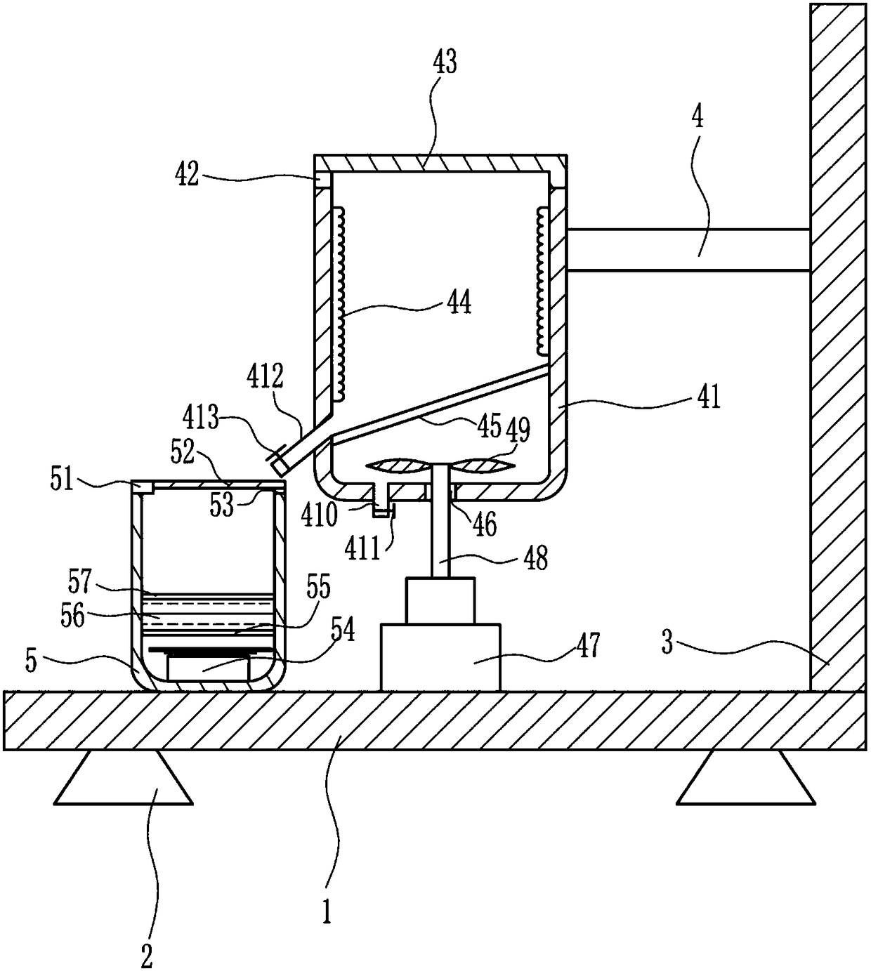
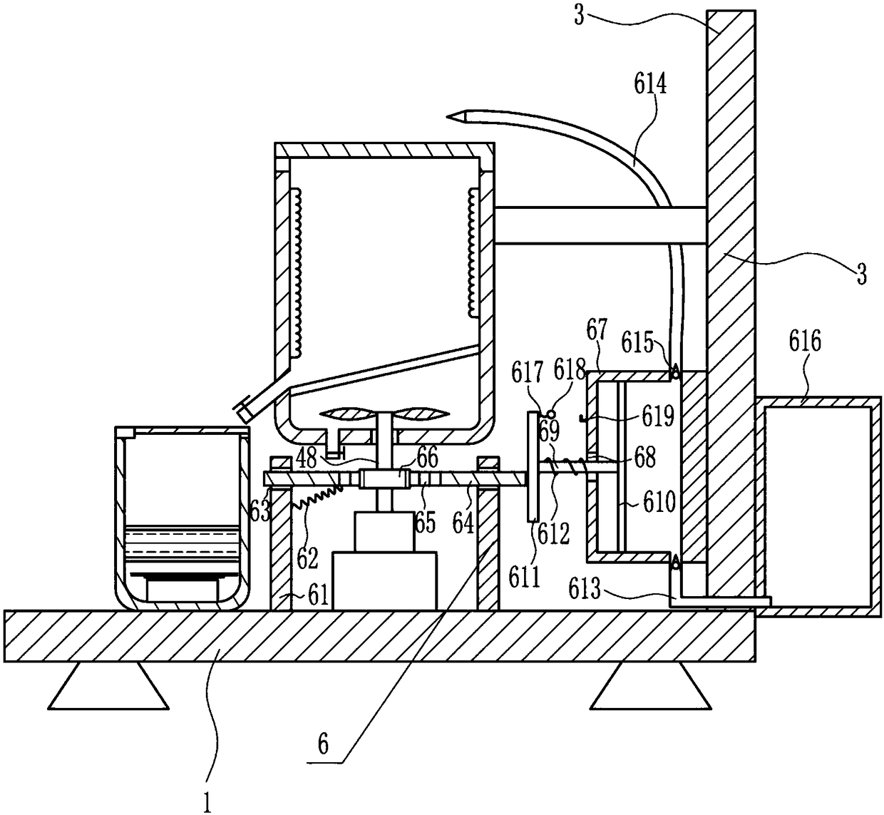
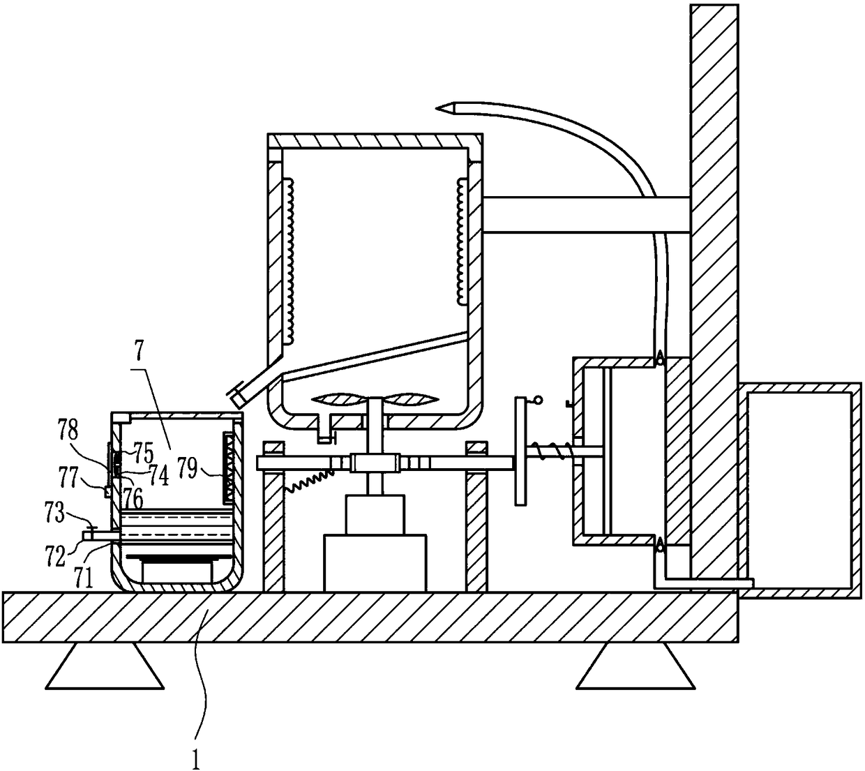
[0028] A medical flow regulator recovery device, such as Figure 1-5 As shown, it includes a bottom plate 1, a support foot 2, a first bracket 3, a second bracket 4, a cleaning bucket 41, a first rotating motor 42, a first cover 43, a bump 44, a leakage plate 45, a first motor 47, and a rotating shaft. 48. Fan blade 49, water outlet pipe 410, first electric valve 411, hollow pipe 412, second electric valve 413, disinfection box 5, second rotating motor 51, second cover 52, rubber pad 53, heating plate 54, stopper The plate 55, the distilled water 56 and the hollow plate 57, the bottom of the bottom plate 1 is connected with the support feet 2, the top right side of the bottom plate 1 is fixedly connected with the first support 3, and the left side of the first support 3 is fixedly connected with the second support 4, A cleaning bucket 41 is fixedly connected to the left end of the second bracket 4 , a first rotating motor 42 is fixedly connected to the top of the left wall of ...

Embodiment 2

[0030] A medical flow regulator recovery device, such as Figure 1-5 As shown, it includes a bottom plate 1, a support foot 2, a first bracket 3, a second bracket 4, a cleaning bucket 41, a first rotating motor 42, a first cover 43, a bump 44, a leakage plate 45, a first motor 47, and a rotating shaft. 48. Fan blade 49, water outlet pipe 410, first electric valve 411, hollow pipe 412, second electric valve 413, disinfection box 5, second rotating motor 51, second cover 52, rubber pad 53, heating plate 54, stopper The plate 55, the distilled water 56 and the hollow plate 57, the bottom of the bottom plate 1 is connected with the support feet 2, the top right side of the bottom plate 1 is fixedly connected with the first support 3, and the left side of the first support 3 is fixedly connected with the second support 4, A cleaning bucket 41 is fixedly connected to the left end of the second bracket 4 , a first rotating motor 42 is fixedly connected to the top of the left wall of ...

Embodiment 3

[0033] A medical flow regulator recovery device, such as Figure 1-5 As shown, it includes a bottom plate 1, a support foot 2, a first bracket 3, a second bracket 4, a cleaning bucket 41, a first rotating motor 42, a first cover 43, a bump 44, a leakage plate 45, a first motor 47, and a rotating shaft. 48. Fan blade 49, water outlet pipe 410, first electric valve 411, hollow pipe 412, second electric valve 413, disinfection box 5, second rotating motor 51, second cover 52, rubber pad 53, heating plate 54, stopper The plate 55, the distilled water 56 and the hollow plate 57, the bottom of the bottom plate 1 is connected with the support feet 2, the top right side of the bottom plate 1 is fixedly connected with the first support 3, and the left side of the first support 3 is fixedly connected with the second support 4, A cleaning bucket 41 is fixedly connected to the left end of the second bracket 4 , a first rotating motor 42 is fixedly connected to the top of the left wall of ...


PUM


Abstract

The invention relates to a recycling device, and particularly relates to a flow rate adjuster recycling device for medical treatment. The technical problem to be solved is to provide a flow rate adjuster recycling device for medical treatment. In order to solve the technical problem, the invention provides the flow rate adjuster recycling device for medical treatment, which comprises a bottom plate, a supporting foot, a cleaning barrel, a first rotating motor, a first cover, a bulge, a leak plate, a first motor, a rotary shaft, a fan, and others; the bottom part of the bottom plate is connected with the supporting foot in all around, the right side at the upper part of the bottom plate is fixedly connected with a first bracket; the left side of the first bracket is fixedly connected with asecond bracket, the left end of the second bracket is fixedly connected with the cleaning barrel. By applying the machine to replace manual work, the recycling device can recycles the flow rate adjuster; the device is quick in recycling rate, and can recycle on a large scale and effectively sterilize, and others; meanwhile, the recycling device is featured by being convenient to use, safe in use,simple in operation, low in manufacturing cost, and others.

Description

technical field [0001] The invention relates to a recovery device, in particular to a recovery device of a medical flow rate regulator. Background technique [0002] Disposable infusion set is a common disposable medical consumable mainly used for intravenous infusion, which has been aseptically processed to establish a channel between vein and medicinal liquid. It is generally composed of venous needle, protective cap, infusion hose, liquid medicine filter, flow rate regulator, drip pot, cork puncture, and air intake pipe air filter. Traditional infusion sets are made of PVC, and high-performance polyolefin thermoplastic elastomer (TPE) is considered to be a safer and higher-performance material for making disposable infusion sets. [0003] There is a serious surplus of ordinary disposable infusion sets, and the market competition can be described as fierce. However, there are still some places that ignore the reality and are still striving for the production of new proje...

Claims


Application Information

Patent Timeline
Patent Type & Authority Applications(China)
IPC IPC(8): A61M5/00
CPCA61M5/00
Inventor 杨月权刘苗方晓晨
Owner ZHEJIANG SANCHUANG BIOTECH
Why Eureka
Try Eureka