Postpartum pelvic floor recovery instrument
A technology of pelvic floor and treatment head, which is applied in the field of medical instruments, can solve the problems of inconvenient operation, high labor cost, and inability to perform other auxiliary therapies, and achieve the effect of convenient operation, better effect and saving labor cost
- Summary
- Abstract
- Description
- Claims
- Application Information
AI Technical Summary
Problems solved by technology
Method used
Image

Examples
Embodiment 1
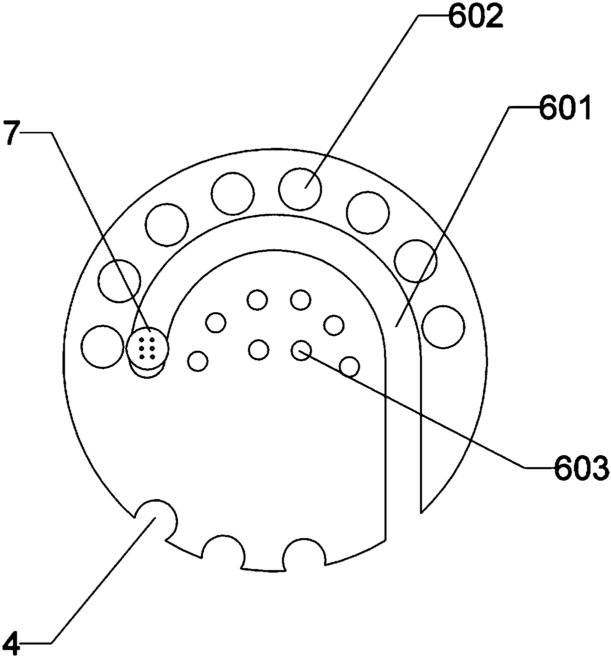
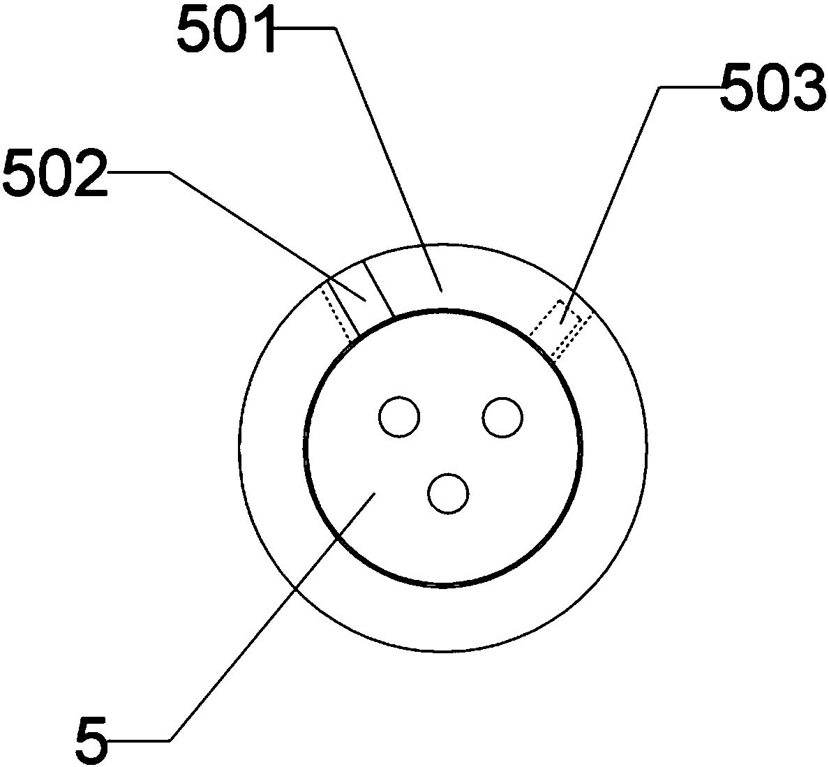
[0034] The reference signs in Embodiment 1 include: box body 1, box cover 2, treatment head resting hole 4, wiring socket 5, chute 501, opening 502, electromagnet bar 503, guide hole 601, electromagnet 602, massage head 603 , clamping portion 604 , jaw 605 , slider 606 , rib 607 , metal object 608 , and treatment head 7 .
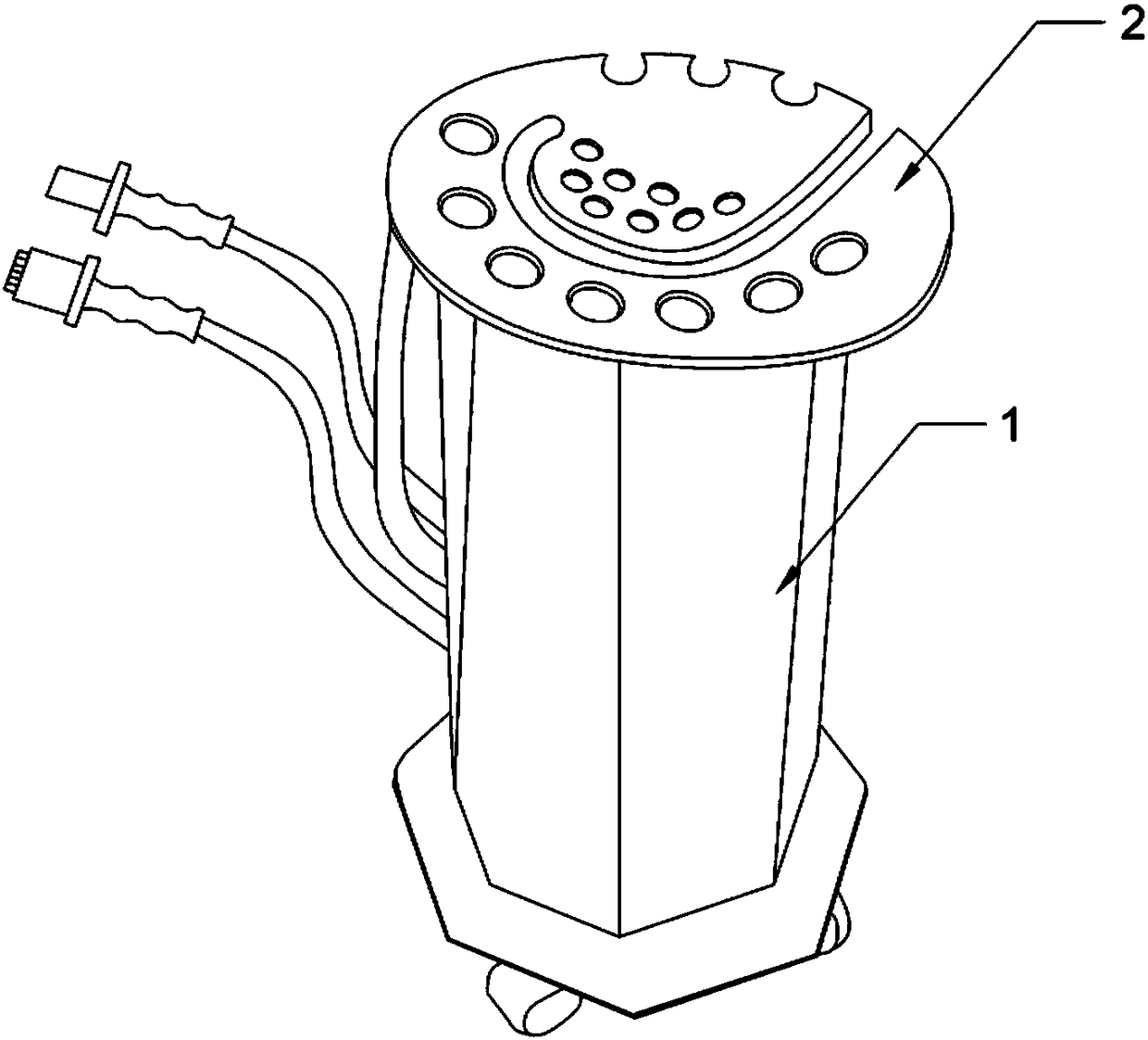
[0035] as attached figure 1 The shown postpartum pelvic floor recovery instrument includes a box body, which can be a hollow polygonal prism or a cylinder. In this embodiment, it is preferably a hollow polygonal prism. The universal wheel of the lock is provided with a box cover 2 detachably connected by bolts on the top of the box body. The outer edge of the box cover 2 in this embodiment protrudes from the side of the box body. The through treatment head rest hole 4, the side opening of the treatment head rest hole 4 towards each treatment head is used to insert each treatment head, there are three treatment head rest holes 4 in the present embodiment, b...
Embodiment 2
[0052] Such as Figure 7 As shown, the reference numerals in this embodiment include: guide chute 301 , guide slide bar 302 , and push switch 303 .
[0053] The difference between this embodiment and Embodiment 1 is that the track of the guide hole opened on the box cover is in the shape of a ring, and a circle of guide chute is opened on the side wall of the guide hole facing the outside. The chute is connected with the mounting holes where the electromagnets are located, and at the position corresponding to each electromagnet on the groove wall of the guide chute, a device is set to electrify the electromagnet when pressed down. Press the switch 303. In this embodiment, after the press switch 303 is pressed, the electromagnet will be charged after a time delay of 5 seconds. The control module described in this embodiment includes each press switch 303 and guide slider 302 One end of the guide slide 302 is fixed to the lower part of the treatment head. Specifically, the conn...
Embodiment 3
[0056] The reference signs in the third embodiment include: covering 801 , electromagnet 802 , treatment head 803 , and metal object 804 .
[0057] Such as Figure 5 As shown, the difference from Embodiment 1 is that in this embodiment, the plurality of electromagnets 802 arrays are arranged on a cover, and the number of electromagnets 802 arrayed in this embodiment is 16, and the cover can be Hard objects, such as plates, can also be soft objects, such as blankets or wearable trousers, blankets are preferred in this embodiment, and the distance between the two adjacent electromagnets 802 is greater than the profile of the treatment head 803 Dimensions, so that the treatment head 803 will not be stuck by the adjacent electromagnet 802 when it moves, and a metal object 804 that can be adsorbed by the electromagnet 802 is provided on the side of the treatment head 803. The metal object 804 is preferred in this embodiment In order to cover the iron layer on the three sides of th...
PUM
 Abstract
Description
Claims
Application Information
 - R&D
- Intellectual Property
- Life Sciences
- Materials
- Tech Scout
- Unparalleled Data Quality
- Higher Quality Content
- 60% Fewer Hallucinations
Browse by: Latest US Patents, China's latest patents, Technical Efficacy Thesaurus, Application Domain, Technology Topic, Popular Technical Reports.
© 2025 PatSnap. All rights reserved.Legal|Privacy policy|Modern Slavery Act Transparency Statement|Sitemap|About US| Contact US: help@patsnap.com