Chemical oxygen self-rescuer

A self-rescuer, chemical oxygen technology, used in life-saving equipment, fire rescue, oxygen-generating respiratory protection devices, etc., can solve problems such as increased cost, increased breathing temperature, insufficient absorption, etc., to improve utilization and reduce breathing resistance. , the effect of reducing the temperature

Pending Publication Date: 2018-06-29
SHAANXI STAR EXPLOSION SAFETY POLYTRON TECH INC
View PDF6 Cites 4 Cited by
  • Summary
  • Abstract
  • Description
  • Claims
  • Application Information

AI Technical Summary

Problems solved by technology

The exhaled gas from this structure enters the oxygen-generating medicine tank from one direction and reacts with the oxygen-generating agent. At this time, the water vapor in the exhaled breath is rushed to the bottom of the medicine tank and concentrates, causing serious agglomeration of the bottom medicine, and the exhalation resistance is at the later stage of the protection time. A sharp rise, the amount of oxygen released in the early stage is higher than that in the late stage, which makes the utilization rate of oxygen lower; because the air flow only passes through the drug layer once, the CO 2 Not absorbed enough
[0005] During the development of the chemical oxygen self-rescuer, after a large number of tests and investigations, the reciprocating structure has obvious advantages in terms of drug utilization and resistance compared with the circulating structure; however, the exhaust valve of the reciprocating structure is often located on the airbag , most of the gas components are oxygen when exhausting, which will lead to aggravated reaction rate, lower drug utilization rate, and increased breathing temperature. In order to reach the rated protection time, it will inevitably lead to increased drug volume and increased cost

Method used


Image

  • Chemical oxygen self-rescuer
  • Chemical oxygen self-rescuer
  • Chemical oxygen self-rescuer

Examples


Embodiment Construction

[0034] Specific embodiments of the present disclosure will be described in detail below in conjunction with the accompanying drawings. It should be understood that the specific embodiments described here are only used to illustrate and explain the present disclosure, and are not intended to limit the present disclosure.

[0035] In the present disclosure, unless stated to the contrary, the used orientation words such as "above and below" usually refer to the definition based on the drawings of the corresponding drawings; "inner and outer" usually refer to the contours of the corresponding components inside and outside; "far and near" are defined based on the drawings of the corresponding drawings. "Cross-sectional area" usually refers to the cross-section along the transverse vertical direction based on the drawing of the corresponding drawing.

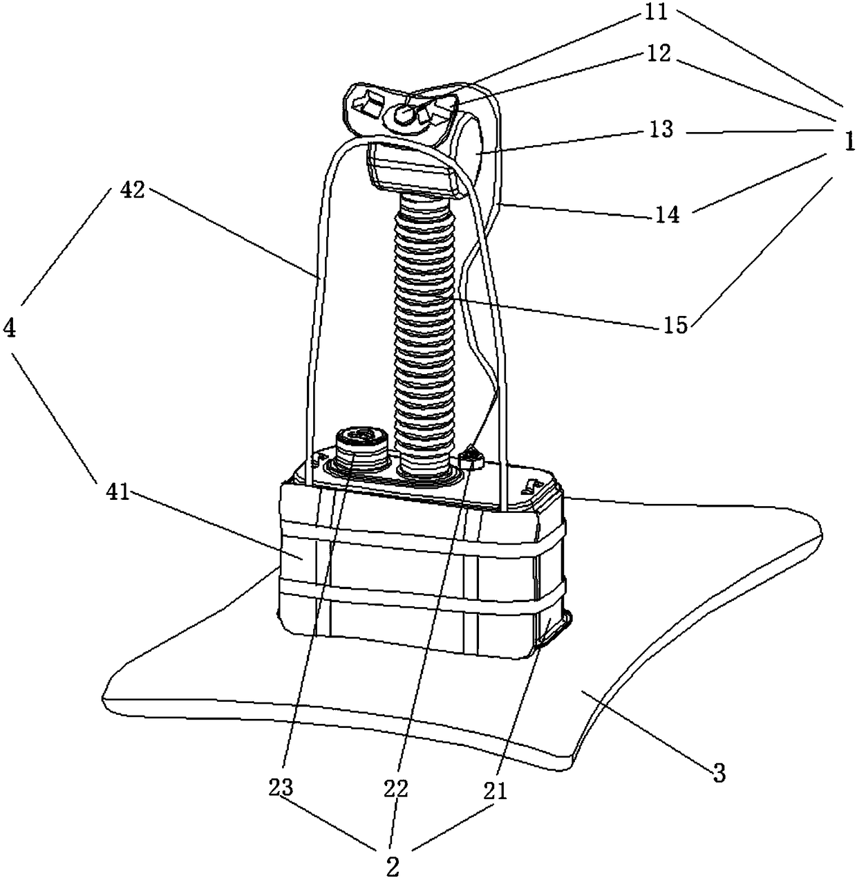
[0036] Such as figure 1 As shown, the chemical oxygen self-rescuer of the present disclosure includes a breathing assembly 1, an o...


PUM


Abstract

The invention discloses a chemical oxygen self-rescuer which comprises a breathing component, an oxygen generation component and an air bag which are sequentially communicated. The oxygen generation component comprises an oxygen generation medicine tank, an air discharging valve and an oxygen candle, the air discharging valve is arranged on a component position above oxygen generation medicines inthe oxygen generation medicine tank and below a breathing end of the breathing component, opening and closing of the air discharging valve are controlled by air inflation volume of the air bag, a cooling component and the oxygen generation medicines are arranged in the oxygen generation medicine tank, the cooling component comprises a vent pipe and a cooling frame, the vent pipe is communicated with the breathing component and the oxygen generation medicine tank, the cooling frame is arranged in the oxygen generation medicine tank, the oxygen generation medicine tank is divided into a plurality of containing spaces for placing the oxygen generation medicine by the vent pipe and the cooling frame, the breathing resistance and the temperature of breathing gas are reduced, and the utilization rate of the oxygen generation medicines is increased.

Description

technical field [0001] The invention relates to safety equipment for coal mines, in particular to a chemical oxygen self-rescuer. Background technique [0002] Self-rescuer products are roughly divided into two categories: reciprocating structure and circular structure. [0003] Reciprocating structure: the inlet and outlet of breathing gas are breathing hoses, the airbag is located at the bottom of the medicine tank, the exhaust valve is generally located on the airbag, and the breathing gas passes through the medicine tank twice. The air flow passes through the medicine tank twice, so that the water vapor that has been blown into the lower layer of the medicine can return to the upper layer. The water vapor can be evenly distributed in the medicine tank and reduce agglomeration. increase. However, because all the breathing gas passes through the medicine tank, the inhalation is also heated, and the breathing temperature is higher, which in turn intensifies the reaction r...

Claims


Application Information

Patent Timeline
Patent Type & Authority Applications(China)
IPC IPC(8): A62B7/08A62B9/02A62B9/04A62B9/00A62B21/00
CPCA62B7/08A62B9/00A62B9/02A62B9/04A62B21/00A62B9/022
Inventor 文新国刘晓伟张龙丁浩李智
Owner SHAANXI STAR EXPLOSION SAFETY POLYTRON TECH INC
Why Eureka
Try Eureka