Centrifugal separation type sand screening device

A centrifugal separation and screening device technology, applied in centrifuges, centrifuges with rotating drums, etc., can solve the problems of reduced work efficiency, high labor intensity, low work efficiency, etc., to reduce labor costs and reduce operations The effect of low strength and equipment cost

Inactive Publication Date: 2018-06-29
杨一诺
View PDF6 Cites 9 Cited by
  • Summary
  • Abstract
  • Description
  • Claims
  • Application Information

AI Technical Summary

Problems solved by technology

In the previous sand screening process, manual operation was usually adopted. Workers used shovels to throw sand and gravel onto the screen, and the sand and gravel slipped from the screen under the action of gravity. During the sliding process, the screening of sand and gravel was completed. High labor intensity and low work efficiency
However, some sand screening machines in the prior art are large in size, complex in structure, and high in economic cost, and are not suitable for household use or small-scale construction sites; sand screening machines with smaller volumes generally have a single function and low efficiency. During the sand screening process, repeated screening is required to separate the sand and stones. The main reason is that the inclination angle of the sand screen mesh of this type of sand screening machine is fixed. The whole process takes a short time, and some sand and gravel have been discharged from the discharge port before they are completely separated. Therefore, it is necessary to screen the sand and gravel several times in order to completely separate the sand and gravel, which not only increases the The labor intensity of the operator also prolongs the working hours, affects the work progress and reduces the work efficiency

Method used


Image

  • Centrifugal separation type sand screening device
  • Centrifugal separation type sand screening device
  • Centrifugal separation type sand screening device

Examples


Embodiment Construction

[0017] The following will clearly and completely describe the technical solutions in the embodiments of the present invention with reference to the accompanying drawings in the embodiments of the present invention. Obviously, the described embodiments are only some of the embodiments of the present invention, not all of them. Based on the embodiments of the present invention, all other embodiments obtained by persons of ordinary skill in the art without making creative efforts belong to the protection scope of the present invention.

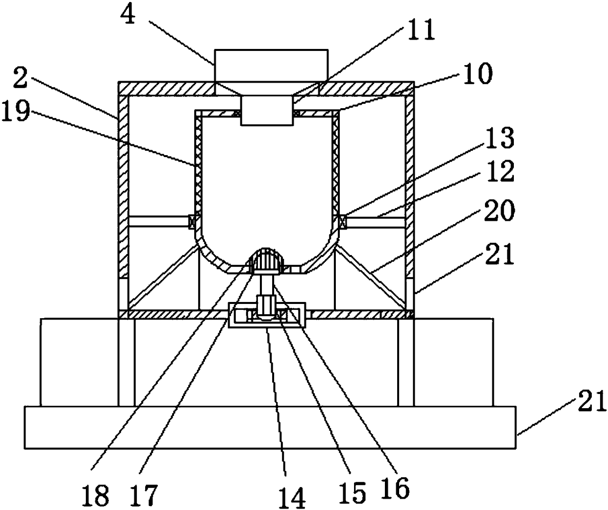
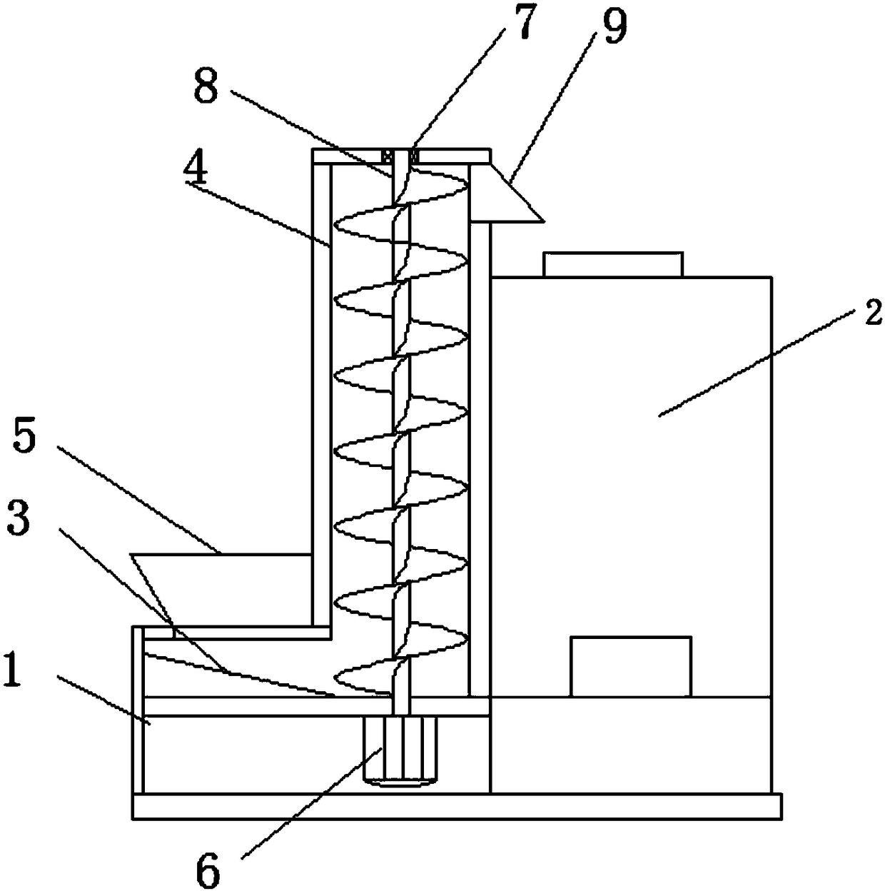
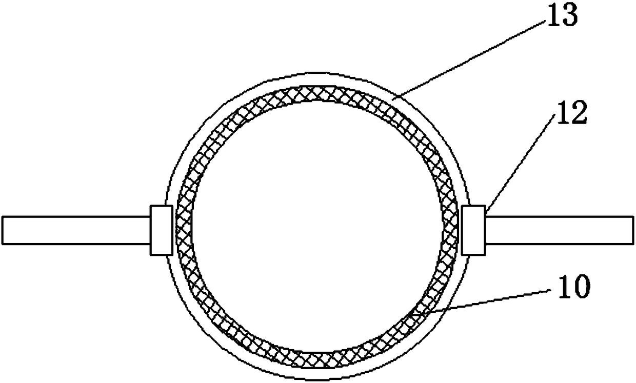
[0018] see Figure 1~3 , in the embodiment of the present invention, a centrifugal separation type sand screening device includes a feeding mechanism 1, a screening box 2 and a base 21, the feeding mechanism 1 is provided with a feeding chamber 3 and a feeding chamber 4, The top of the feeding chamber 3 is provided with a feeding hopper, the feeding chamber 3 communicates with the bottom of the feeding chamber 4, the bottom of the feeding chamber...


PUM


Abstract

The invention discloses a centrifugal separation type sand screening device comprising a transporting mechanism, a screen box and a base. An inner cavity of the screen box is provided with a centrifugal barrel of which the top end is provided with a feeding hopper, and the feeding hopper is located below a transport port obliquely; the inner cavity of the screen box is provided with a fixed framewhich is provided with a fixed sleeve, and the centrifugal barrel is installed in the fixed sleeve; the middle position of the bottom end of the screen box is provided with a driving motor of which the top end is provided with a rotating shaft, and the top end of the rotating shaft is provided with a convex gear block; the bottom end of the centrifugal barrel is provided with a concave gear slot,and the convex gear block is embedded into the concave gear slot; and the side wall of the centrifugal barrel is provided with a filter screen, and the inner bottom end of the screen box is provided with guide plates of which the tail ends are provided with discharging ports. According to the sand screening device, through centrifugal motion, sand is screened effectively, and the sand screening device is applicable for screening fine sand; and the quality of filtered gains of sand can be guaranteed effectively.

Description

technical field [0001] The invention relates to the construction field, in particular to a centrifugal separation type sand screening device. Background technique [0002] During construction, it is often necessary to screen sand and gravel to remove stones or subdivide sand and gravel so that the screened sand meets the requirements of construction. In the previous sand screening process, manual operation was usually adopted. Workers used shovels to throw sand and gravel onto the screen, and the sand and gravel slipped from the screen under the action of gravity. During the sliding process, the screening of sand and gravel was completed. The operation is labor-intensive and the work efficiency is low. However, some sand screening machines in the prior art are large in size, complex in structure, and high in economic cost, and are not suitable for household or small-scale construction sites; small sand screening machines generally have a single function and low efficiency. ...

Claims


Application Information

Patent Timeline
Patent Type & Authority Applications(China)
IPC IPC(8): B04B3/00B04B7/18B04B11/04B04B9/08
CPCB04B3/00B04B7/18B04B9/08B04B11/04
Inventor 杨一诺
Owner 杨一诺
Why Eureka
Try Eureka