
Copper wire coiling device

A wire roll and equipment technology, applied in the field of winding equipment, can solve problems such as inconvenience, loose winding, and complexity, and achieve the effects of avoiding heat accumulation, convenient use, and uniform winding

Active Publication Date: 2018-06-29
中海宏祥铜业江苏有限公司
View PDF6 Cites 2 Cited by
  • Summary
  • Abstract
  • Description
  • Claims
  • Application Information

AI Technical Summary

Problems solved by technology

[0003] The amount of copper wire used is very large. During the copper wire production process, the copper wire needs to be wound on the bobbin for subsequent transportation and storage. The existing copper wire winding equipment is relatively complicated, the cost is high, and it does not have copper wire cooling. Function, because the copper wire has just been produced, its temperature is high, although it is cooled by the cooling equipment, the temperature is still high, if the copper wire is not cooled again, it will easily cause the wound copper wire to become loose after cooling, which is very inconvenient

Method used


Image

  • Copper wire coiling device
  • Copper wire coiling device

Examples


Embodiment Construction

[0018] The technical solution of this patent will be further described in detail below in conjunction with specific embodiments.

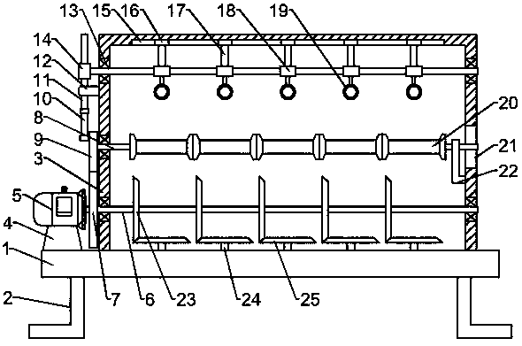
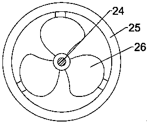
[0019] see Figure 1-2 , a copper wire winding device, comprising a fixed base plate 1, a support frame 3 is fixedly connected above the fixed base plate 1, a motor base 4 is fixedly connected to the left side above the fixed base plate 1, and a motor 5 is fixedly connected above the motor base 4, The output end of the motor 5 is fixedly connected with a first rotating shaft 6, the left end of the first rotating shaft 6 is fixedly connected with a driving gear 7, and the upper part of the first rotating shaft 6 is rotatably connected with a second rotating shaft 8, and the second rotating shaft 8 rotates with the support frame 3 connected, the left end of the second shaft 8 is fixedly connected with a driven gear 9, the driven gear 9 is meshed with the driving gear 7, and the eccentric position on the upper left side of the driven gear 9 is rotatab...


PUM


Abstract

The invention discloses a copper wire coiling device. The copper wire coiling device comprises a fixed bottom plate. A supporting frame is fixedly connected to the upper portion of the fixed bottom plate. A motor base is fixedly connected to the left side of the upper portion of the fixed bottom plate. A motor is fixedly connected to the upper portion of the motor base. The output end of the motoris fixedly connected with a first rotary shaft. The left end of the first rotary shaft is fixedly connected with a driving gear. A second rotary shaft is rotatably connected to the portion above thefirst rotary shaft. The second rotary shaft is rotatably connected with the supporting frame. The left end of the second rotary shaft is fixedly connected with a driven gear. The driven gear is engaged with the driving gear. A first driving rod is rotatably connected to the eccentric position of the upper portion of the left side of the driven gear. Compared with the prior art, the copper wire coilign device has the beneficial effects that the copper wire coiling device is simple in structure, convenient to use and capable of winding multiple copper wires simultaneously in the using process; meanwhile, the copper wire coiling device can effectively prevent the copper wires from pushing each other in the winding process and is uniform in winding and capable of cooling the copper wires in the winding process and avoiding heat accumulation.

Description

technical field [0001] The invention relates to a winding device, in particular to a copper wire winding device. Background technique [0002] In life, copper wires are used as conductors. Good electrical conductivity, widely used in the manufacture of wires, cables, brushes, etc.; good thermal conductivity, often used to manufacture magnetic instruments and instruments that must prevent magnetic interference, such as compass, aviation instruments, etc.; excellent plasticity, easy to hot press and Cold pressure processing can be made into copper materials such as tubes, rods, wires, strips, strips, plates, and foils. [0003] The amount of copper wire used is very large. During the copper wire production process, the copper wire needs to be wound on the spool for subsequent transportation and storage. The existing copper wire winding equipment is relatively complicated, the cost is high, and it does not have copper wire cooling. Function, because the copper wire has just b...

Claims


Application Information

Patent Timeline
IPC IPC(8): B21C47/12B21C47/26
Inventor 叶春鸣吴峰陶智朱合启何秀荣
Owner 中海宏祥铜业江苏有限公司
Learn More