
Reinforcement cage for drilled press-grouting piles and molding device thereof

A technology of forming device and reinforcement cage, which is applied in application, sheet pile wall, household appliances, etc., can solve the problems of destroying the continuity of concrete layer and insufficient structural strength at the connection of reinforcement cage units, and achieves convenient assembly, simple structure, and improved The effect of connection strength

Active Publication Date: 2018-06-29
C KIS CONSTR CO LTD
View PDF8 Cites 3 Cited by
  • Summary
  • Abstract
  • Description
  • Claims
  • Application Information

AI Technical Summary

Problems solved by technology

[0004] The cited documents point out in claim 9 that both the first connector and the second connector are plates, so if Figure 12 As shown in , when the concrete and the reinforcement cage are poured and fixed, the first connector and the second connector will cut off the concrete layer, thereby destroying the continuity of the concrete layer at this position, and resulting in insufficient structural strength at the joint of the two reinforcement cage units The problem

Method used


Image

  • Reinforcement cage for drilled press-grouting piles and molding device thereof
  • Reinforcement cage for drilled press-grouting piles and molding device thereof
  • Reinforcement cage for drilled press-grouting piles and molding device thereof

Examples


Embodiment 1

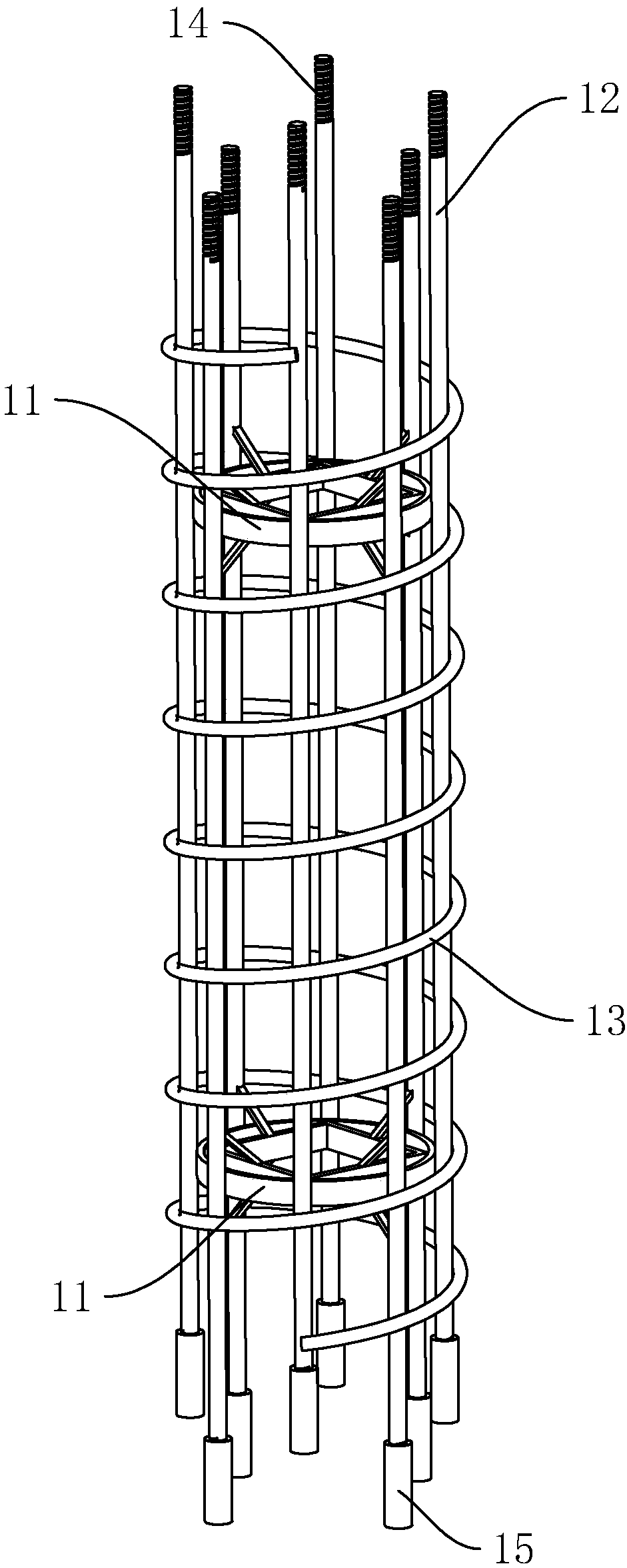
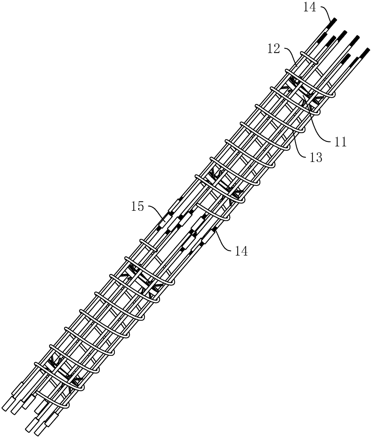
[0045] Example 1: Reinforcement cage used for bored piles, such as figure 1 As shown, it includes at least two steel cage units, which are connected end to end. The steel cage unit includes two stiffening hoops 11 arranged oppositely, eight main steel bars 12 welded and fixed to the two stiffening hoops 11 at the same time, and spiral coils. Spiral hoops 13 wound around eight main steel bars 12 and welded and fixed. Each main steel bar 12 is provided with external threads 14 at the upper and lower ends. The lower external threads 14 are threaded with a connecting sleeve 15, and the upper and lower ends of the connecting sleeve 15 are For the opening structure.

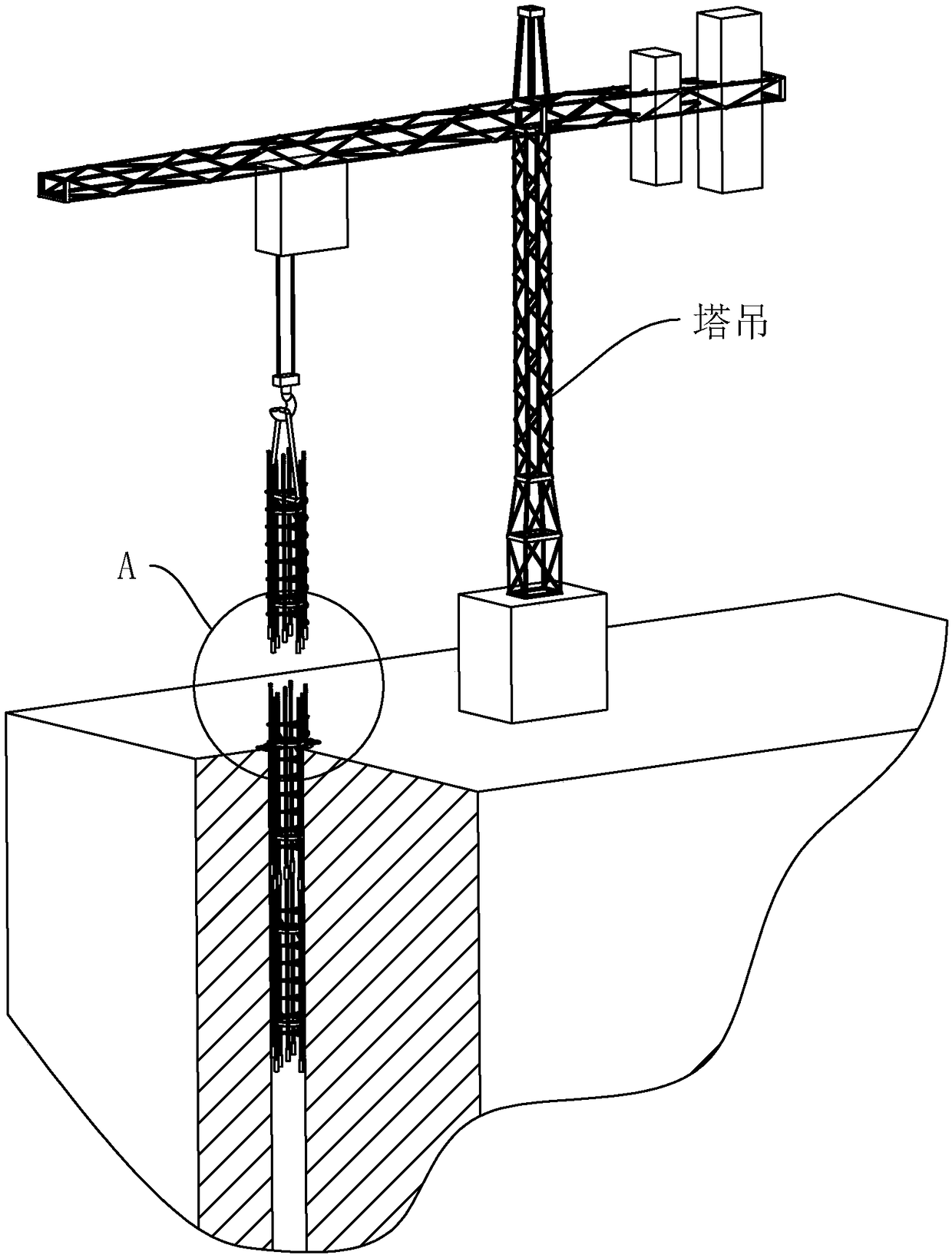
[0046] When the pile hole is drilled and the reinforcement cage needs to be buried, such as Figure 2-4 As shown, the first steel cage unit is vertically hung by a tower crane. When the first steel cage unit is lowered to the upper stiffener 11 and 10 cm from the ground, the suspension stops, and two rectangular steel bar...

Embodiment 2

[0051] Example 2: Molding device, such as Figure 8-10 As shown, it includes two horizontal guide rails 2, a fixing frame 21 fixedly arranged at one end of the horizontal guide rail 2, a sliding frame 22 sliding along the horizontal guide rail 2 and a hoop mechanism; the fixing frame 21 is rotatably connected with a disc 23 with a round surface There are eight sockets 24 for inserting and mating with the main steel bars 12; the sliding frame 22 is rotatably connected with a turntable 27, the turntable 27 is opposite to the circular surface of the disk 23, and eight main steel bars 12 are welded and fixed along the circumference of the turntable 27. The plug sleeve 28 passing through, the plug sleeve 28 and the socket 24 correspond one-to-one; the circular disc 23 and the turntable 27 are respectively horizontally provided with extension posts 25 at the center of the circle, and the adjacent ends of the two extension posts 25 are respectively welded and fixed with four The arm 2...


PUM


Abstract

The invention discloses a reinforcement cage for drilled press-grouting piles and a molding device thereof, and aims to solve the problem of weak structural strength in the connecting place of two reinforcement cage units. The reinforcement cage for the drilled press-grouting piles comprises at least two sections of reinforcement cage units; and the reinforcement cage units are connected end to end; the reinforcement cage units comprise two opposite stiffening ribs, multiple main reinforcements fixed with the two stiffening ribs at the same time, and spiral hoops spirally fixed with the multiple main reinforcements. The reinforcement cage for the drilled press-grouting piles is characterized in that external threads are arranged at the upper and lower ends of the main reinforcements; the external threads on the lower sides are in threaded fit with connecting sleeves; and the upper and lower ends of the connecting sleeves are of opening structures. The reinforcement cage for the drilledpress-grouting piles realizes connection of the two reinforcement cage units through cooperation between the connecting sleeves and the external threads, so that separation of concrete caused by connection of the two reinforcement cage units is prevented, and the structural strength in the connecting place of the reinforcement cage units is improved.

Description

Technical field [0001] The invention relates to the field of engineering construction, and more specifically, it relates to a reinforcing steel cage used for bored piles and its forming device. Background technique [0002] Cast-in-place bored piles are piles made by drilling a pile hole with a drilling machine, placing a steel cage in the hole, and finally pouring concrete into the pile. It is mainly used for the construction of high-rise buildings and bridges; When the steel cage is inserted into the hole, the length of the steel cage is limited, and there is a problem that it is difficult to install. [0003] In order to solve the above problems, the Chinese Patent Announcement No. CN107142925A discloses a steel cage and a method for manufacturing steel cages. The technical point is that it includes at least two steel cage units, the steel cage units are connected end to end, and the steel cage also includes at least one Connecting devices, each connecting device is used for fi...

Claims


Application Information

Patent Timeline
Patent Type & Authority Applications(China)
IPC IPC(8): B21F27/20E02D5/34
CPCB21F27/20E02D5/34
Inventor 庄千杰庄千军楼星柳锡丹朱姿丰方理丹
Owner C KIS CONSTR CO LTD
Learn More