
Semi-blind hole forge piece hole-shrinking forging method

A semi-blind hole and forging technology, applied in the field of metal plastic forming, can solve the problems of raw material waste, increased forging difficulty, and hidden safety hazards, and achieve the effects of reducing production process consumption, improving internal metal structure, and reducing machining allowance

Active Publication Date: 2018-06-29
HENAN ZHONGYUAN SPECIAL STEEL EQUIP MFG CO LTD
View PDF5 Cites 3 Cited by
  • Summary
  • Abstract
  • Description
  • Claims
  • Application Information

AI Technical Summary

Problems solved by technology

[0004] The disadvantages of the above method: Method 1) The wall thickness of the forging is increased, the raw materials are wasted, and the forging design is often too heavy due to the large gap between the product apertures, and the size of the mandrel used in the forging process is caused by the small end aperture. Too small to bear too much weight, increasing the difficulty of forging, and there are safety hazards in the production process
Method 2) Forging of solid forgings is easy to achieve, but the internal quality of the product is not easy to guarantee, and it is difficult to machine holes, resulting in serious waste of raw materials, long processing time, and excessive machining allowance
In addition, the forgings produced by the above two methods will destroy the metal fibers of the forgings when machining the semi-blind hole end, which will adversely affect the performance of the product

Method used


Image

  • Semi-blind hole forge piece hole-shrinking forging method
  • Semi-blind hole forge piece hole-shrinking forging method
  • Semi-blind hole forge piece hole-shrinking forging method

Examples


Embodiment Construction

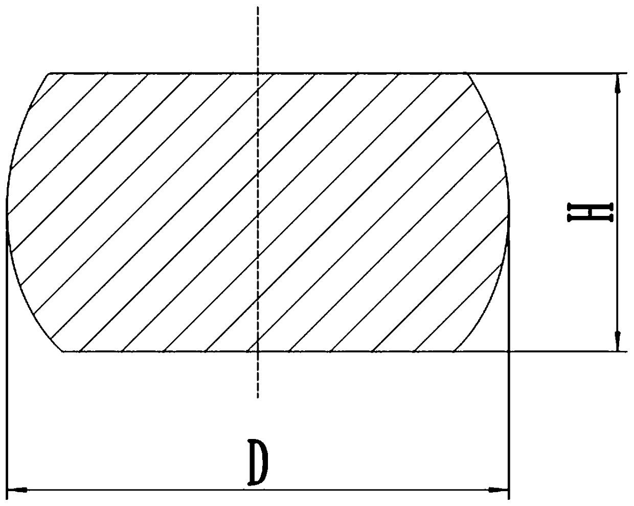
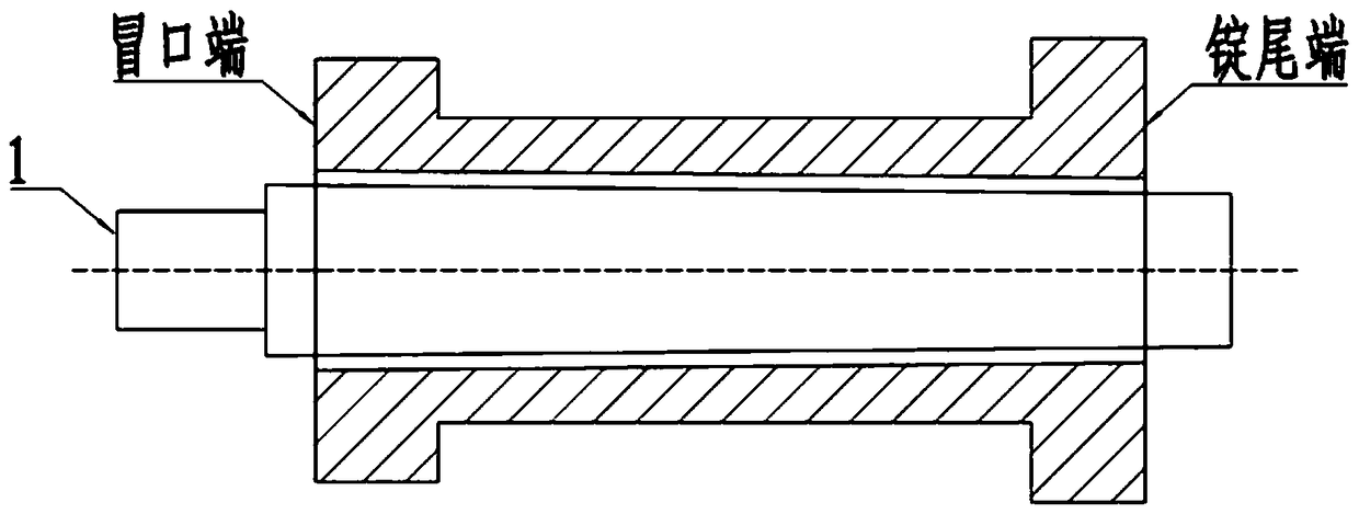
[0023] The technical solution of the present invention is achieved in this way: a method for forging a semi-blind hole forging, comprising the following steps:

[0024] Step 1), stagger the tail of the ingot and chop the riser;

[0025] Step 2), upsetting;

[0026] Step 3), punching with a solid punch;

[0027] Step 4), use the horse bar to ream the hole until the large diameter end of the traditional common mandrel can penetrate the blank for elongation;

[0028] Step 5), use the traditional common mandrel to draw and grow to the preform;

[0029] Step 6), upsetting the vertical material, and flattening the end surface of the blank;

[0030] Step 7), forming the hole;

[0031] Step 8), finishing the surface.

[0032] Figure 5 Shown is a finished product drawing of a semi-blind forging after the hole is closed, and both ends of the semi-blind forging are semi-blind.

[0033] The raw material of the semi-blind forging is a die-cast steel ingot. When the forging producti...


PUM


Abstract

The invention provides a semi-blind hole forge piece hole-shrinking forging method. According to the semi-blind hole forge piece forging method, a traditional tool is used for achieving the forge piece hole-shrinking process by changing the deformation process of a material and controlling deformation. The method mainly comprises the following steps of (1) flattening the tail of an ingot and cutting a dead head flat; (2) conducting upsetting; (3) punching a hole with a solid punch pin; (4) broadening the hole through a mandrel until the big-diameter end of a traditional common core rod can penetrate into a blank to be drawn out; (5) drawing out the traditional common core rod to form a preformed blank; (6) erecting the blank to conduct upsetting and smoothening the end faces of the blank;(7) conducting hole-shrinking forming; and (8) conducting surface finishing. Through the method, raw materials are saved; the cost of the raw materials is lowered; the machining allowance is reduced;the machining time is shortened; the production efficiency is improved; consumption during the production process is reduced; the internal metal structure and metal flow line at the intersection of steps of an inner hole of a forge piece are improved, and a continuous metal fibrous structure of the forge piece is maintained after machining; the anti-fatigue performance of the forge piece is improved, and the service life of the forge piece is prolonged.

Description

technical field [0001] The invention belongs to the technical field of metal plastic forming, and relates to a hole-receiving forging method of a semi-blind hole forging. Background technique [0002] With the development of science and technology, users have higher and higher requirements for product quality and performance, and the product structure should also adopt an integral structure as much as possible. Semi-blind hole parts are processed and manufactured as a whole. Since both ends of the product are semi-blind holes, there is a large gap between the end diameter of the inner hole and the middle part of the product. The shape and structure are special, and the traditional forging method cannot be directly forged. [0003] The forging method usually adopted for such semi-blind hole products: 1) Increase the wall thickness of the forging, forging it into a common hollow forging, and then forming it by machining. During forging, the diameter of the inner hole needs to...

Claims


Application Information

Patent Timeline
IPC IPC(8): B21J1/00B21J5/08B21J5/10B21J5/00
CPCB21J1/00B21J5/002B21J5/08B21J5/10
Inventor 王文高全德张庆雷宋小波孙振环许长军
Owner HENAN ZHONGYUAN SPECIAL STEEL EQUIP MFG CO LTD
Learn More