Mechanical device for resistance spot welding

A mechanical device, resistance spot welding technology, applied in resistance welding equipment, resistance electrode bases, electrode features, etc., can solve the problems of rising construction costs and material costs, damage to the signal line of the servo motor, and adjustment of the upper and lower moving and static arms. Achieve the effect of improving the standardized design of the clamp body, improving the design efficiency and manufacturing efficiency, and simplifying the structure

Pending Publication Date: 2018-06-29
韦孚(杭州)精密机械有限公司
View PDF8 Cites 2 Cited by
  • Summary
  • Abstract
  • Description
  • Claims
  • Application Information

AI Technical Summary

Problems solved by technology

The disadvantage of this spot welding device is that the upper and lower movable and static arms cannot be adjusted with the diversification of products, and it is a fixed structure, resulting in many types of pliers; It will cause damage to the signal line of the servo motor; and the trunnion bushing needs to be replaced regularly, resulting in an increase in construction cost and material cost; the positive and negative poles of the transformer have an asymmetric structure, and when the positive and negative poles need to be replaced, the clamp body or the conductive block needs to be modified. Causes high cost of transformation; in short, complex structure, low utilization rate, high cost of product use

Method used


Image

  • Mechanical device for resistance spot welding
  • Mechanical device for resistance spot welding
  • Mechanical device for resistance spot welding

Examples


Embodiment Construction

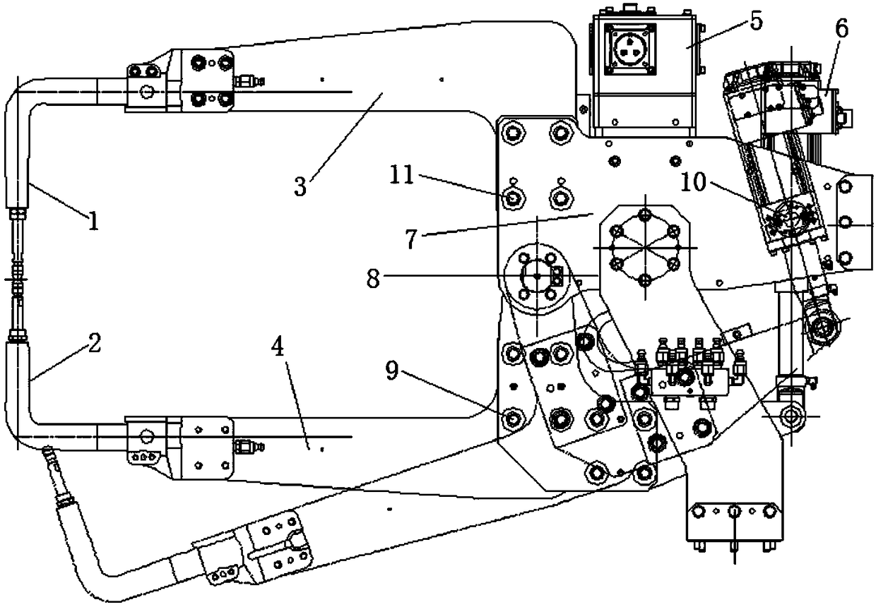
[0016] According to attached figure 2 As shown, the present invention discloses a mechanical device for resistance spot welding, which includes a welding tongs body, an integrated servo motor 16 connected to the welding tongs body, and a transformer 26 connected to the welding tongs body. The welding tongs body includes an upper electrode 12. The lower electrode 13, the boom 14, the static arm 15, the boom seat 19, the clamp body 23 and the clamp body support shaft 27, the upper electrode 12 and the lower electrode 13 are set up and down relative to the working position, and the upper electrode 12 is set on the swing arm 14, the lower electrode 13 is set on the static arm 15, the mounting hole 29 is reserved on the movable arm base 19, and the mounting hole 30 is also reserved on the static arm base. The servo motor 16 is connected to the clamp through the servo fixing screws 25 on both sides. body 23, the end of the servo motor 16 is provided with a flange 24, the push rod o...


PUM


Abstract

The invention discloses a mechanical device for resistance spot welding. The mechanical device for resistance spot welding comprises a soldering pliers body, an integrated servo motor connected to thesoldering pliers body and a transformer connected to the soldering pliers body, wherein the soldering pliers body comprises an upper electrode, a lower electrode, a movable arm, a stationary arm, a movable arm base, a pliers body and a pliers body supporting shaft; the upper electrode and the lower electrode are arranged up and down according to a working position; mounting holes are reserved inthe movable arm seat and a stationary arm seat; the servo motor is connected to the pliers body through servo fixing screws on two sides; a flange is arranged on the end part of the servo motor; a push rod of the servo motor is connected to the movable arm seat through a hinge block; the pliers body supporting shaft is arranged in the middle of the pliers body; the pliers body supporting shaft isconnected to a fixed side plate of the transformer; a water distributor is arranged on the upper part of the fixed side plate of the transformer; the pliers body is connected to a spring balancing mechanism; and a conducting block and a conducting bar are arranged between the fixed side plate of the transformer and the pliers body. The mechanical device for resistance spot welding disclosed by theinvention achieves a modular standardized design of the soldering pliers body, is compact in structure and convenient to replace, and the utilization ratio of the equipment is improved.

Description

technical field [0001] The invention belongs to the field of welding, and in particular relates to a mechanical device for resistance spot welding. Background technique [0002] The structure of the existing technology is complex, some of the clamp body materials are casting materials, and some are of relatively complicated design structures, resulting in various product models and many spare parts for operation, resulting in high cost for customers. [0003] attached figure 1 The structure of the existing spot welding device is shown. The electrodes 1 and 2 are up and down, and the static arm 3 at the upper end and the movable arm 4 at the lower end are respectively connected to the upper part of the caliper body 7 through the fixed arm fixing screw 11 and the moving arm fixing screw 9. and the lower part, the upper and lower parts of the pliers body are connected to each other through the caliper body shaft 8, the transformer 5 is arranged on the upper end of the pliers b...

Claims


Application Information

Patent Timeline
Patent Type & Authority Applications(China)
IPC IPC(8): B23K11/11B23K11/36B23K11/31
CPCB23K11/11B23K11/31B23K11/36
Inventor 张学洋
Owner 韦孚(杭州)精密机械有限公司
Why Eureka
Try Eureka