Pneumatic tire

A technology for pneumatic tires and treads, applied in tire parts, tire treads/tread patterns, transportation and packaging, etc., can solve problems such as failure to suppress partial partial wear of main ribs

Inactive Publication Date: 2018-06-29
TOYO TIRE & RUBBER CO LTD
View PDF13 Cites 2 Cited by
  • Summary
  • Abstract
  • Description
  • Claims
  • Application Information

AI Technical Summary

Problems solved by technology

For example, Patent Document 2 ( figure 1 , 2 ), Patent Document 3 ( figure 2 ), the groove bottom of the narrow groove is formed so that only the groove wall on the side that becomes the tread end side is depressed. In this configuration, it is considered that the above-mentioned partial partial wear of the main rib due to the ground contact pressure distribution cannot be suppressed.

Method used


Image

  • Pneumatic tire
  • Pneumatic tire
  • Pneumatic tire

Examples


Embodiment Construction

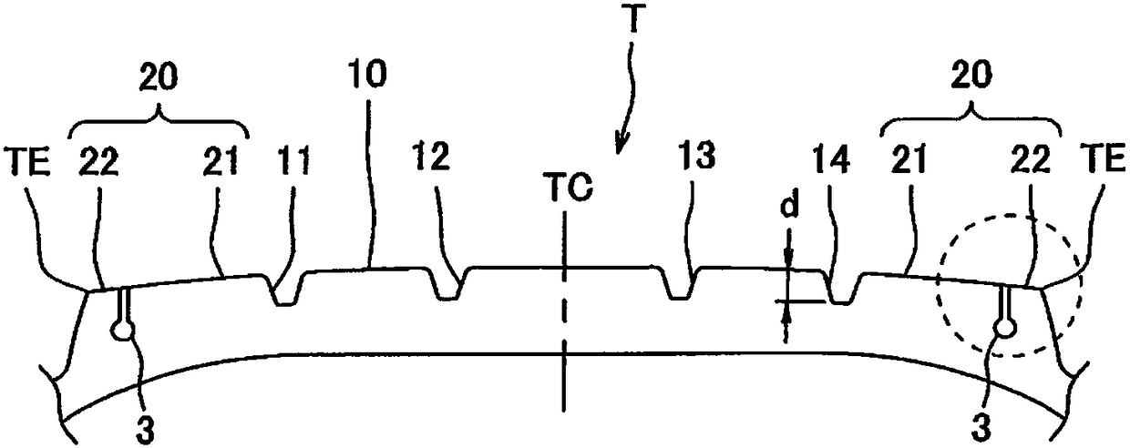
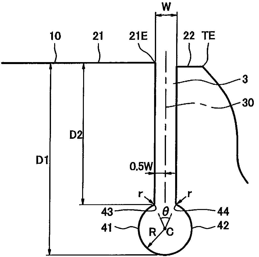
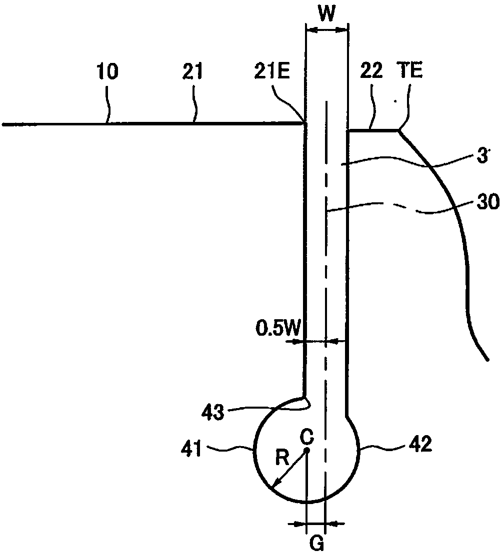
[0023] Embodiments of the present invention will be described with reference to the drawings. figure 1 The tread 10 of the pneumatic tire T of this embodiment is schematically shown. figure 2 Enlarged to show figure 1 The main part of the is surrounded by a dotted box.

[0024] This pneumatic tire T has, like a normal pneumatic tire, a pair of beads not shown and a pair of sidewalls extending radially outward from the beads, and the tread 10 is provided on each of the sidewalls. The radially outer ends of the tires are connected. In addition, a carcass extending in an annular shape is provided between a pair of beads, and reinforcing members such as a belt for reinforcing the carcass are embedded in the tread 10 , but illustration of these is omitted.

[0025] A plurality of main grooves extending in the tire circumferential direction are formed on the tread 10 , and in the present embodiment, four main grooves 11 to 14 are formed. The tread 10 is divided into a plurality...


PUM


Abstract

The invention provides a pneumatic tire in which a narrow groove extending in a tire circumferential direction is formed in a shoulder land portion of a tread, and which is excellent in a groove bottom crack resistance, a tear resistance and an irregular wear resistance. In the pneumatic tire where a narrow groove (3) which extends in a tire circumferential direction and is formed in a shoulder land portion of a tread (10), an inside concave curved surface (41) and an outside concave curved surface (42) are formed in a groove bottom portion of the narrow groove (3), the inside concave curved surface (41) being formed by depressing a groove wall in a tread center side, and the outside concave curved surface (42) being formed by depressing a groove wall in a tread end TE side, wherein an inner surface of the groove bottom portion including the inside concave curved surface (41) and the outside concave curved surface (42) is formed by a single circular arc in a tire meridian cross section, and wherein a radius of curvature (R) of the circular arc is equal to or larger than a width (W) of an opening portion of the narrow groove.

Description

technical field [0001] The present invention relates to a pneumatic tire in which thin grooves extending in the tire circumferential direction are formed on shoulder land portions of a tread. Background technique [0002] Conventionally, a pneumatic tire is known in which narrow grooves extending in the tire circumferential direction are formed on shoulder ribs (an example of a shoulder land portion) of a tread. The shoulder ribs are divided into main ribs on the tread center side and sacrificial ribs on the tread end side by the thin grooves. In the tire configured in this way, wear can be concentrated on the sacrificial ribs, so wear of the main ribs is suppressed, and uneven wear resistance is improved. The fine grooves are also called defensive grooves, and are mainly formed in pneumatic tires used for heavy loads such as trucks and buses. [0003] However, if the tire lands on a curb or the like and a large force is applied to the shoulder land portion, deformation ma...

Claims


Application Information

Patent Timeline
Patent Type & Authority Applications(China)
IPC IPC(8): B60C11/04B60C11/13
CPCB60C11/04B60C11/13B60C11/01B60C11/1353B60C2011/0353B60C2011/0348
Inventor 长谷田弘到
Owner TOYO TIRE & RUBBER CO LTD
Why Eureka
Try Eureka