

Testing device for hovering characteristics of pendulum type rotor system of Mars unmanned aerial vehicle
A characteristic test and aircraft rotor technology, applied in the direction of measuring device, aircraft component test, machine/structural component test, etc., can solve problems such as difficult to simulate accurate test of rotor performance, achieve novel measurement methods, scientific and reasonable structural design, and test The effect of stable performance indicators
- Summary
- Abstract
- Description
- Claims
- Application Information
AI Technical Summary
Problems solved by technology
Method used
Image

Examples
specific Embodiment approach 1
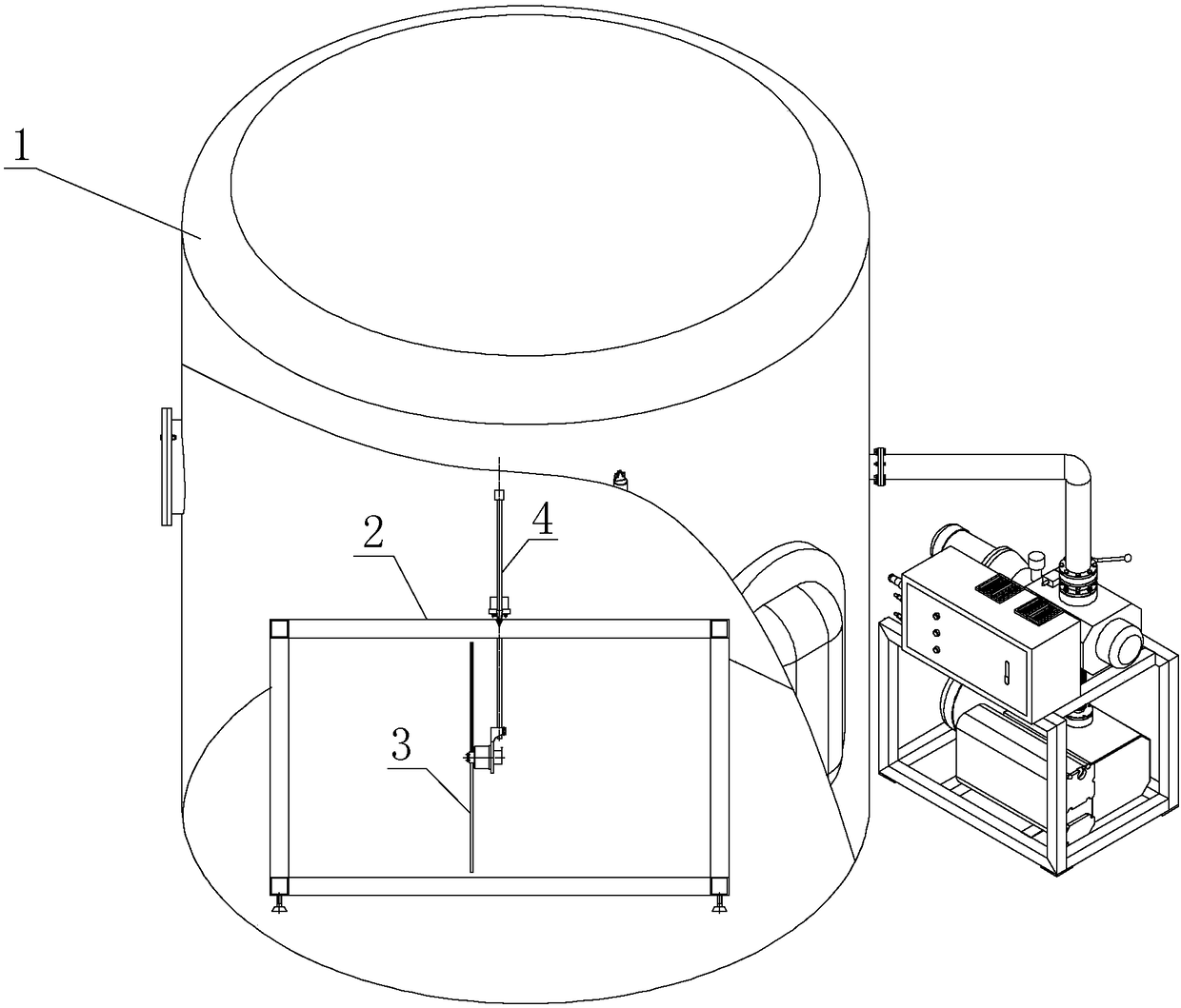
[0036] Specific implementation mode one: see figure 1 Describe this embodiment, a kind of pendulum-type Mars unmanned aerial vehicle rotor system hovering characteristic testing device described in this embodiment, it comprises Mars atmospheric environment simulation device 1, support frame 2, rotor system 3 and swing angle detection device 4;
[0037] The support frame 2 is placed in the Mars atmospheric environment simulation device 1, and the rotor system 3 and the swing angle detection device 4 are fixed on the support frame 2;
[0038] The rotor system 3 is used to generate rotor lift in the horizontal direction;
[0039] The swing angle detection device 4 is used to detect the swing angle value of the rotor connecting rod 3-1 on the rotor system 3 under different rotor lift forces.
[0040] In this embodiment, the support frame 2, the rotor system 3 and the swing angle detection device 4 are placed in the Mars atmospheric environment simulation device 1, and the rotor p...
specific Embodiment approach 2
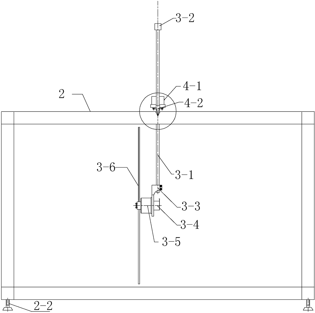
[0041] Specific implementation mode two: see Figure 1 to Figure 6 Describe this embodiment, the difference between this embodiment and the pendulum-type Mars UAV rotor system hovering characteristic test device described in the first embodiment is that the rotor system 3 includes a rotor connecting rod 3-1, a counterweight Block 3-2, connecting rod seat 3-3, photoelectric encoder 3-4, motor 3-5 and rotor blade 3-6;
[0042] The head end of the rotor connecting rod 3-1 is fixed with a counterweight 3-2, and the tail end is fixed with a connecting rod seat 3-3, and the rotor connecting rod 3-1 is fixed on the support frame 2;
[0043] The photoelectric encoder 3-4 and the motor 3-5 are all fixed on the connecting rod seat 3-3, the photoelectric encoder 3-4 is used to detect the rotating speed of the motor 3-5, and the output shaft of the motor 3-5 is fixed with a rotor blade Leaves 3-6.
[0044] In this embodiment, the rotor connecting rod 3-1 and the connecting rod base 3-3 ...
specific Embodiment approach 3
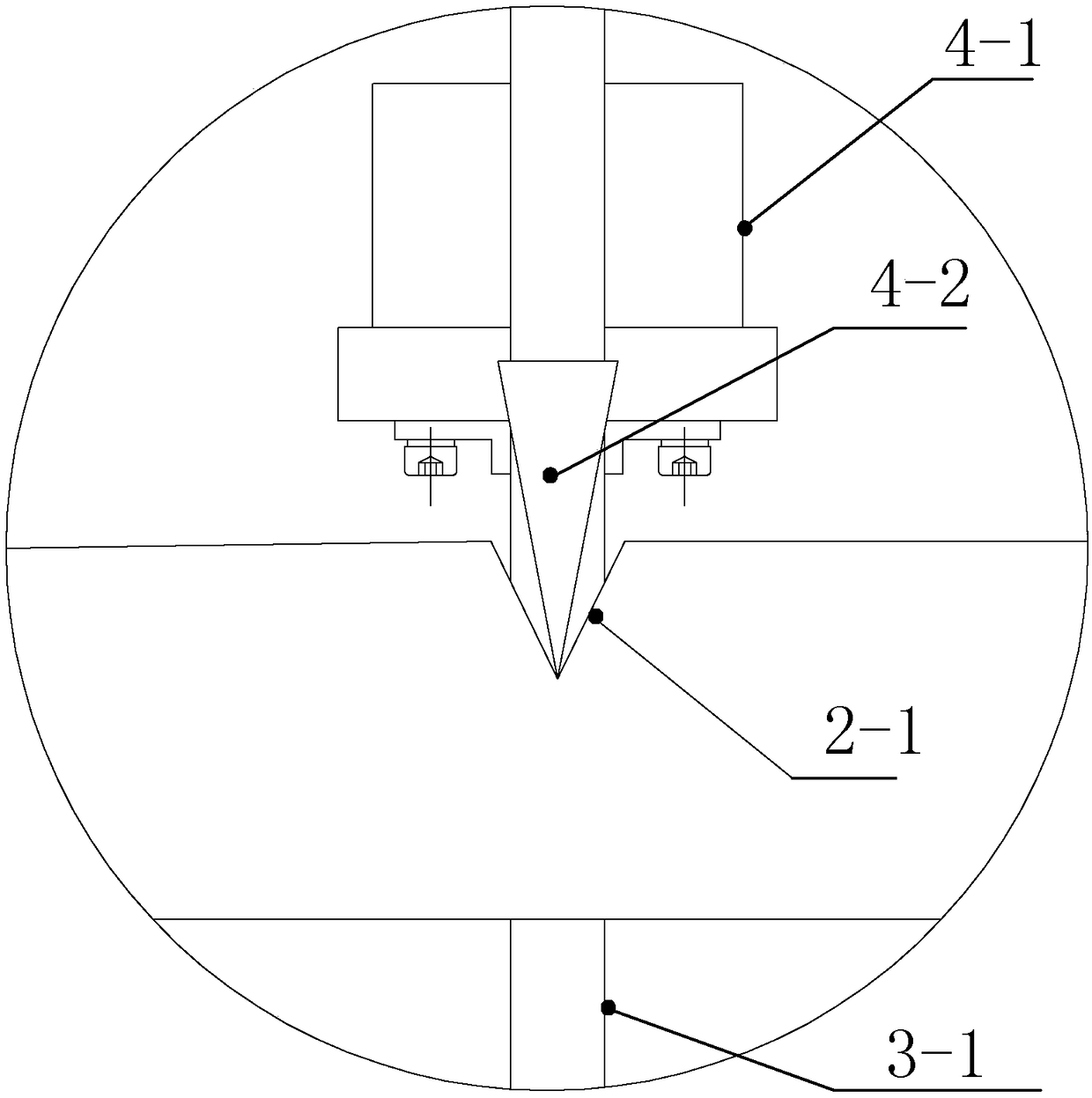
[0045] Specific implementation mode three: see Figure 1 to Figure 6 Describe this embodiment, the difference between this embodiment and a pendulum-type Mars unmanned aerial vehicle rotor system hovering characteristic test device described in the second embodiment is that the pendulum angle detection device 4 includes an inclinometer 4-1, two A knife-edge support 4-2 and a knife-edge connecting rod 4-3;
[0046] The front and rear two support rods of the upper end surface of the support frame 2 are all provided with a knife-edge groove 2-1, and a knife-edge support 4-2 is respectively arranged in the two knife-edge grooves 2-1, and the blade of the knife-edge support 4-2 The tip is in line contact with the knife-edge groove 2-1;
[0047] Two knife-edge brackets 4-2 are respectively fixed on the two ends of the knife-edge connecting rod 4-3, and the knife-edge connecting rod 4-3 is vertically fixed on the rotor connecting rod 3-1,
[0048] The inclinometer 4-1 is fixed on the...
PUM
 Abstract
Description
Claims
Application Information