Novel color changing device for computerized flat knitting machine

A computerized flat knitting machine, a new type of technology, applied in textiles and papermaking, weft knitting, knitting, etc., can solve the problems of controlling the position of the ejector pin at any position in the middle, low reliability of the electromagnet structure, and unstable operation of the electromagnet. It achieves the effect of rich yarn feeder knitting state design, convenient and reliable installation and maintenance, and small vibration

Pending Publication Date: 2018-06-29
QUANZHOU YONGQI PLASTIC ELECTRON
View PDF8 Cites 1 Cited by
  • Summary
  • Abstract
  • Description
  • Claims
  • Application Information

AI Technical Summary

Problems solved by technology

This structure has defects such as high noise, unstable electromagnet action, easy overheating, or insufficient magnetic suction. At the same time, because the electromagnet only has two working states, one stretching and one shrinking, the corresponding ejector rod movement has only two working positions, which cannot Control the position of the ejector rod at any position in the middle to meet the working requirements corresponding to different working positions of the ejector rod. The original electromagnet structure has low reliability and single working state, which cannot meet the existing production needs.

Method used


Image

  • Novel color changing device for computerized flat knitting machine
  • Novel color changing device for computerized flat knitting machine
  • Novel color changing device for computerized flat knitting machine

Examples


Embodiment Construction

[0019] The following will clearly and completely describe the technical solutions in the embodiments of the present invention with reference to the accompanying drawings in the embodiments of the present invention. Obviously, the described embodiments are only some, not all, embodiments of the present invention. Based on the embodiments of the present invention, all other embodiments obtained by persons of ordinary skill in the art without making creative efforts belong to the protection scope of the present invention.

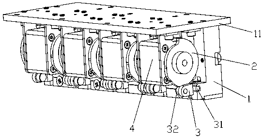
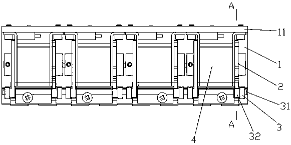
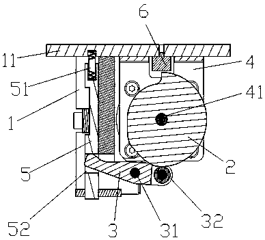
[0020] see figure 1 , figure 2 , image 3 , the present invention provides a technical solution: a new color changing device for a computerized flat knitting machine, including a base body 1 and a ejector device assembly, the ejector device assembly is arranged in four sets on the base body 1, the ejector device The rod device assembly includes a push rod 5, a swing rod 3, a cam 2 and a motor drive device 4. A seat plate 11 is provided on the seat body 1. T...


PUM


Abstract

The invention discloses a novel color changing device for a computerized flat knitting machine, which comprises a seat body and a mandril device component; the mandril device component is provided with several groups of seat bodies, and the mandril device component comprises a mandril, a swaying rod, a cam and a motor driving device; a seat plate is arranged on the seat body, the motor driving device is fixed on the seat plate; the cam is connected with the motor driving device, and the mandril is moveably embedded on the seat body; a supporting spring is arranged between the upper end of themandril and the seat plate, the sway rod is hinged to one side of the lower end of the seat body; the front end of the sway rod is sleeved to the lower end of the mandril, and the back end thereof isbonded to the lower part of the periphery of an outline of the cam; an inductive sensor corresponding to the upper part of the cam is arranged on the seat plate. The whole structure realizes the conversion of three working positions of vertically moved mandril; the mandril position is correspondingly controlled to move to the required height by adopting an equal pitch contour section of differentzone sections of the cam; the structure is small in working noise, stable in action, and can meet the using demands of different production states.

Description

technical field [0001] The invention relates to the technical field of computerized knitting, in particular to a novel color changing device for computerized flat knitting machines. Background technique [0002] The function of the color-changing device of the existing computerized flat knitting machine is to drive the yarn feeder to move laterally according to pattern programming needs to drive the yarn feeder to weave. Most structures use electromagnets to control the height and position of the ejector rod. This structure has defects such as high noise, unstable electromagnet action, easy overheating, or insufficient magnetic suction. At the same time, because the electromagnet only has two working states, one stretching and one shrinking, the corresponding ejector rod movement has only two working positions, which cannot The position of the ejector rod is controlled at any position in the middle, so as to meet the work and use requirements corresponding to different work...

Claims


Application Information

Patent Timeline
Patent Type & Authority Applications(China)
IPC IPC(8): D04B15/70
CPCD04B15/70
Inventor 杨鹭晖臧兆建杨明海吕聪雕
Owner QUANZHOU YONGQI PLASTIC ELECTRON
Why Eureka
Try Eureka