Deformation joint structure

A deformation joint and variable technology, which is applied in the field of deformation joint structure, can solve the problems of functional limitation, increase of engineering cost, and influence on the beauty of buildings, etc., and achieve the effects of easy processing and production, beautiful appearance and structure, and good waterproof effect

Inactive Publication Date: 2018-06-29
刘坤贤
View PDF6 Cites 2 Cited by
  • Summary
  • Abstract
  • Description
  • Claims
  • Application Information

AI Technical Summary

Problems solved by technology

In order to solve the deformation problems caused by uneven settlement, earthquake resistance and temperature of large buildings, deformation joints of a certain width are set in advance at the parts that are more likely to be deformed, that is, the buildings are disconnected, so that each part after disconnection becomes an independent unit. The design code clearly stipulates the setting of deformation joints, which solves the problems of building settlement, earthquake resistance, deformation, etc., but if these deformation joints are not well decorated, it will not only affect the beauty of the building but also limit the use function
[0003] In the prior art, there are many ways to deal with deformation joints, but the effect is general
There are also finished deformation joint cover plates on the market, which are generally made of metal, and the construction process is complicated, the cost is high, and the engineering cost is significantly increased, so it is not suitable for large-scale construction

Method used


Image

  • Deformation joint structure
  • Deformation joint structure
  • Deformation joint structure

Examples


Embodiment Construction

[0022] The specific implementation manners of the present invention will be further described below in conjunction with the drawings and examples. The following examples are only used to illustrate the technical solution of the present invention more clearly, but not to limit the protection scope of the present invention.

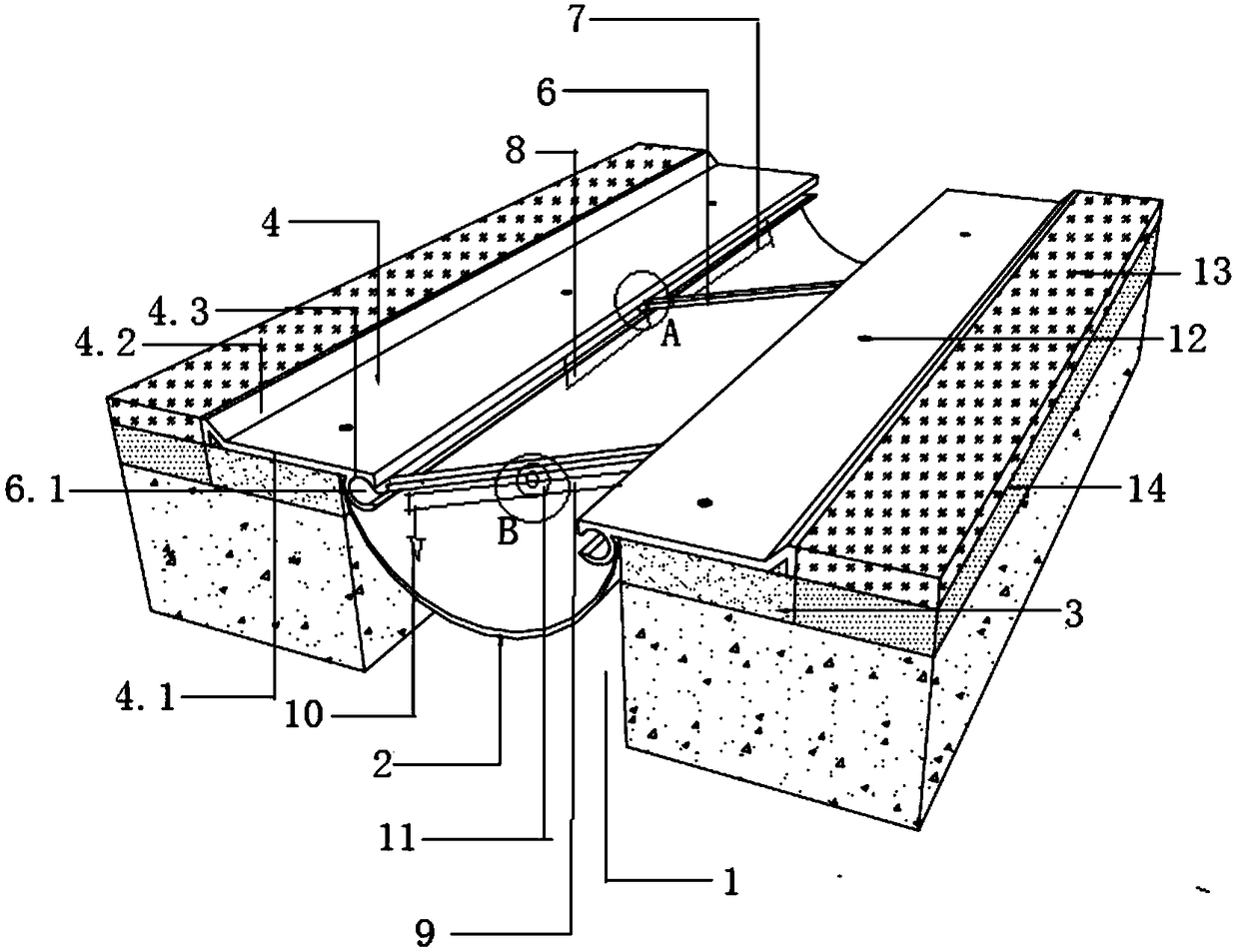
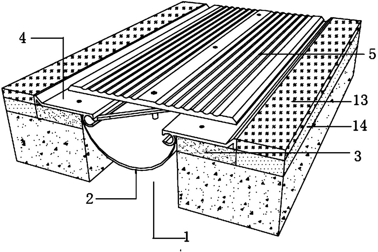
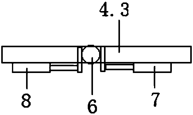
[0023] like Figure 1~5 As shown, the present invention is a deformation joint structure, and the deformation joint structure includes a water stop 2 arranged between the deformation joints 1. The water stop 2 is an arc-shaped surface that is concave toward the deformation joint. The lower surfaces on both sides are connected to the cushion layer 3 arranged on the edge of the deformation joint 1, the upper surfaces on both sides of the waterstop 1 are pressed under the installation base 4, and the deformation joint cover is installed on the installation base 4 Plate 5, the installation base 4 is a tensile profile, the cross section of the deformation joint...


PUM


Abstract

The invention discloses a deformation joint structure. The deformation joint structure comprises a water stop strip, wherein the water stop strip is arranged in the deformation joint; pad layers arranged on the edges of the deformation joint are connected with the lower surface of the two sides of the water stop strip, and the upper surface of the two sides of the water stop strip is pressed undermounting base seats; a deformation joint cover plate is installed on the upper surface of the mounting base seats, wherein the mounting base seats are made from stretch sectional materials; the crosssections of the mounting base seats comprise straight sections used for installing the deformation joint cover plate, a V-shaped groove is formed in one end of each straight section, and a C-shaped groove is formed in the other end of each straight section; the C-shaped grooves arranged on the mounting base seats of the two sides of the deformed joint are symmetrical to each other, and a plurality of sliding bars are installed between the pair of C-shaped grooves arranged symmetrically; and ball heads matched with the C-shaped grooves are arranged on the two ends of the sliding bars, and thedeformed joint cover plate is connected with the sliding bars through fastening pieces. The deformed joint structure has the characteristics of simple structure, beautiful shape and structure, convenient processing and producing, good water-proof effect and the like, and the deformation quantity of the deformed joint can be measured.

Description

technical field [0001] The invention relates to the technical field of covering treatment of deformation joints in buildings, in particular to a deformation joint structure. Background technique [0002] Due to factors such as temperature difference and settlement of buildings, the deformation of the wall surface of the structure may be caused, especially for large-scale and high-rise buildings with various shapes, high and low, and different styles, which makes the deformation of the building more complicated. In engineering construction, walls often appear Surface deformation seams need to be dealt with. In order to solve the deformation problems caused by uneven settlement, earthquake resistance and temperature of large buildings, deformation joints of a certain width are set in advance at the parts that are more likely to be deformed, that is, the buildings are disconnected, so that each part after disconnection becomes an independent unit. The design code clearly stipu...

Claims


Application Information

Patent Timeline
Patent Type & Authority Applications(China)
IPC IPC(8): E04B1/68
CPCE04B1/68E04B1/6803E04B1/6806
Inventor 刘坤贤
Owner 刘坤贤
Why Eureka
Try Eureka