
Protective safety net

A safety net and crossbar technology, applied in door/window protection devices, shutters/movable grilles, railings, etc., can solve the problems of high labor intensity, low efficiency, large space occupation, etc., and achieve fast and simple installation. Easy and fast operation, neat and beautiful appearance

Inactive Publication Date: 2018-06-29
郴州八方农林科技有限公司
View PDF0 Cites 0 Cited by
  • Summary
  • Abstract
  • Description
  • Claims
  • Application Information

AI Technical Summary

Problems solved by technology

Since the protective net is made into a whole first and then installed in windows, corridors and other safety protection openings, the overall protective net itself is heavy, takes up a large space, and is inconvenient to transport
Secondly, due to the heavy weight of the protective net itself and the large space occupied, the installation is labor-intensive and the installation efficiency is low, resulting in high cost and low economic benefit. operation, which endangers the personal safety of the installer and is inconvenient
Thirdly, because only temporary processing methods can be used, the size must be measured in advance or booked according to the drawings, which cannot realize mass production and pre-storage in advance, and cannot be flexibly adjusted according to the actual situation. The production, processing and construction period is long, the efficiency is low, and the quality is poor.

Method used


Image

  • Protective safety net
  • Protective safety net

Examples


Embodiment Construction

[0026] The present invention is described in detail below in conjunction with accompanying drawing and specific embodiment:

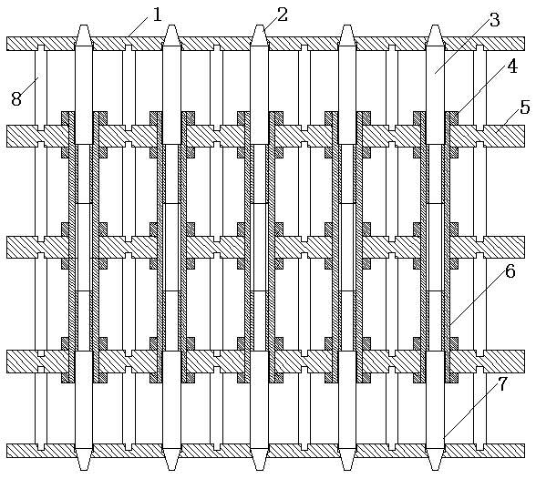
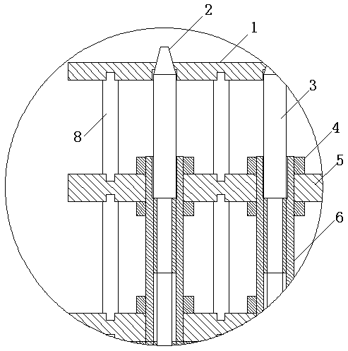
[0027] Such as figure 1 , figure 2 As shown, the protective safety net of the present invention includes a pole set, and the pole set is composed of at least two poles. The pole comprises a pole a3, a pole b7 and a connecting sleeve 6. The vertical rod a3 and the vertical rod b7 are respectively provided with threaded connection ends. The screw threads of the vertical rod a3 and the vertical rod b7 are screwed into the same direction of rotation. The two ends of the connecting rod or the connecting sleeve 6 are respectively provided with threads compatible with the threaded openings of the vertical rod a3 and the vertical rod b7. The vertical rod a3 and the vertical rod b7 are connected through the connecting sleeve 6 to form a vertical rod, and the screwing of the connecting sleeve 6 can make the two ends of the vertical rod or the cross bar retra...


PUM


Abstract

The invention discloses a protective safety net. The protective safety net comprises a vertical rod group or a transverse rod group, and the vertical rod group or horizontal rod group consist of at least two vertical or horizontal rods. The vertical or horizontal rods include a vertical rod a or a transverse rod a, a vertical rod b or a transverse rod b, and connecting rods or connecting sleeves,and the vertical rod a or the transverse rod a, and the vertical rod b or the transverse rod b are separately provided with screw connection ends. The screw-into rotation direction of a threaded opening of the vertical rod a or the transverse rod a is the same as that of the vertical rod b or the transverse rod b, and the two ends of the connecting rods or the connecting sleeves are separately provided with threads suitable for the threaded openings of the vertical rod a or the transverse rod a and the vertical rod b or the transverse rod b. The vertical rod or the transverse rod is formed bythe vertical rod a or the transverse rod a and the vertical rod b or the transverse rod b through the connecting rods or the connecting sleeves, and the two ends of the vertical rod or the transverserod can be retracted or extended at the same time by the screwed connecting rods and the connecting sleeves.

Description

technical field [0001] The invention relates to a protective device, in particular to a protective safety net. Background technique [0002] Windows and corridors of houses are generally equipped with protective nets for safety protection. At present, the use of protective nets is a temporary production and processing method that is welded and fixed into a whole according to the specific dimensions of windows, corridors, etc., and then fixed at safety protection openings such as windows and corridors. Because the protective net is first made into a whole and then installed in safety protection openings such as windows and corridors, the overall protective net has a large weight and takes up a large area of ​​space, which is inconvenient for transportation. Secondly, due to the heavy weight of the protective net itself and the large space occupied, the installation is labor-intensive and the installation efficiency is low, resulting in high cost and low economic benefit. Th...

Claims


Application Information

Patent Timeline
Patent Type & Authority Applications(China)
IPC IPC(8): E06B9/06E04F11/18
CPCE06B9/06E04F11/181E04F11/1844E04F11/1846E04F11/1848E06B9/0623
Inventor 张平伟
Owner 郴州八方农林科技有限公司
Learn More