Active and semi-active electromagnetic vibration suppression system

An electromagnetic vibration, semi-active technology, applied in vibration suppression adjustment, non-rotation vibration suppression, spring/shock absorber, etc., can solve problems such as no data collected, no explanation or report found, etc., to achieve rich functions and save power The effect of resources, simple structure

Inactive Publication Date: 2018-06-29
SHANGHAI JIAO TONG UNIV
View PDF10 Cites 3 Cited by
  • Summary
  • Abstract
  • Description
  • Claims
  • Application Information

AI Technical Summary

Problems solved by technology

[0003] At present, there is no description or report of the similar technology of t

Method used


Image

  • Active and semi-active electromagnetic vibration suppression system
  • Active and semi-active electromagnetic vibration suppression system
  • Active and semi-active electromagnetic vibration suppression system

Examples


specific Embodiment 1

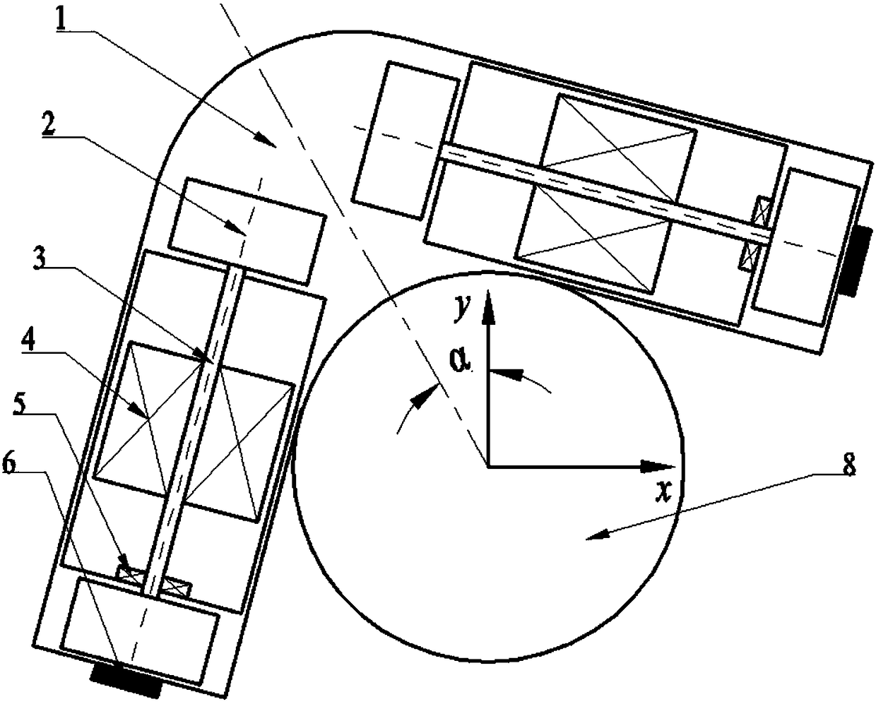
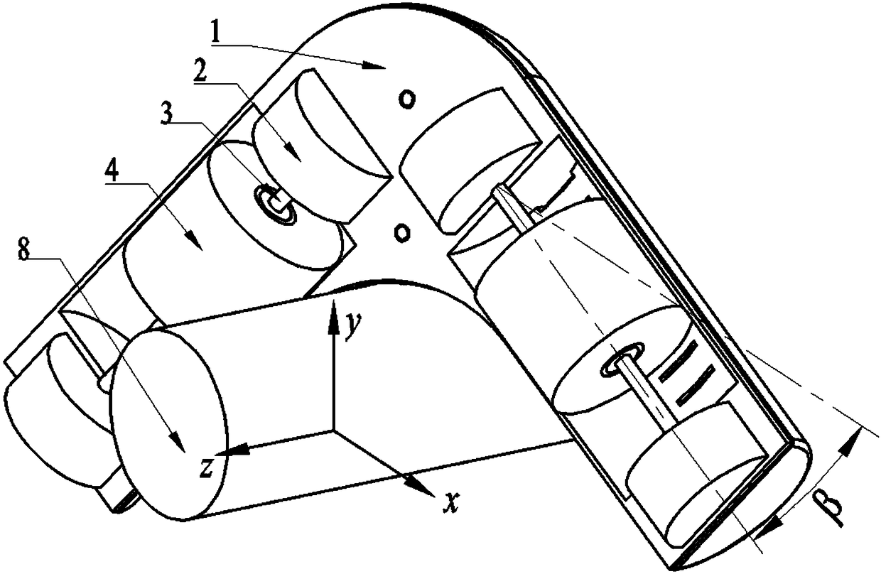
[0060] figure 2 is a modification based on the basic embodiment. The vibration suppression device is deflected by a certain angle β around the y-axis. Since the electromagnetic spring also has a stiffness component in the z-direction, the vibration in the 8-axis direction of the isolated object can also be suppressed, so that the device can decompose the vibration from any direction in space. Vibration suppression is performed for the three directions of x, y, and z.

specific Embodiment 2

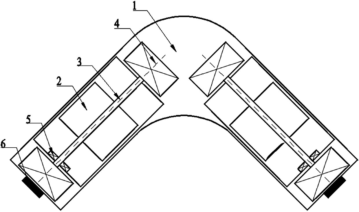
[0062] image 3 It is a semi-active electromagnetic vibration suppression combination device for permanent magnet movement, similar to the basic embodiment, but the positions of the electromagnetic coil 4 and the permanent magnet 2 are interchanged, the electromagnetic coil is fixed, and the permanent magnet 2 can slide freely on the shaft and connect with the energized electromagnetic coil 4 forms an electromagnetic spring, and the driving principle is similar to that of the basic embodiment, except that the induced voltage in the magnetoelectric sensor 5 is generated by the motion of the permanent magnet.

specific Embodiment 3

[0064] Figure 4 It is a deformation of the specific embodiment 2, and it is also a semi-active electromagnetic vibration suppression combination device for permanent magnet movement. The difference is that there are only two symmetrically arranged electromagnetic coils 4 in the device, and the permanent magnet 2 is sleeved in the electromagnetic coil 4. There is a small gap with the inner wall of the electromagnetic coil 4, so that the permanent magnet can move in the axial direction. After the electromagnetic coil 4 is energized, an electromagnetic spring is formed between the electromagnetic coil 4 and the permanent magnet. The permanent magnet can be a whole permanent magnet or a plurality of permanent magnets spliced ​​together.


PUM


Abstract

The invention provides an active and semi-active electromagnetic space vibration suppression system. The system is characterized in that each electromagnetic coil and corresponding permanent magnets are arranged on the same axis, and the same structures are symmetrically arranged so as to restrain vibration in the other direction; when a certain included angle exists between the symmetrical structures in the space, vibration of the three-dimensional space can also be restrained; when the electromagnetic coils or the permanent magnets can freely move on shafts, magnitude of direct currents in the electromagnetic coils is adjusted, so that the coils or the permanent magnets are always subjected to repulsive force to form electromagnetic springs; rigidity of the electromagnetic springs is adjusted, and then the inherent frequency of a device is adjusted; when the inherent frequency is the same as the vibration frequency of a separated system, vibration can be restrained in a semi-active mode; and when both the electromagnetic coils or the permanent magnets are fixed, the frequency and the amplitude of alternating currents in the electromagnetic coils are adjusted, then the active force can be formed, and the proper active force acts on the separated system, so that vibration can be actively restrained. According to the active and semi-active electromagnetic space vibration suppression system, the device is simple in structure, capable of restraining vibration in multiple directions, wide in effective working frequency band and diversified in change form.

Description

technical field [0001] The invention relates to the technical fields of vibration control and electrostatic-electromagnetic interaction, in particular to an active and semi-active electromagnetic vibration suppression system. Background technique [0002] Machines are widely used as the driving force in industry and transportation, the hazards of mechanical vibration are becoming more and more serious, and the requirements for vibration control are becoming more and more urgent. Power machinery such as steam turbines, water turbines, and motors, transportation tools such as automobiles, trains, ships, and airplanes, as well as machine tools, mining machinery, and construction machinery, etc., are all developing in the direction of high speed and heavy load, and their vibrations are becoming increasingly intense. In the development of precision machine tools and precision machining technology, if you leave the quiet environment with strict vibration isolation, the work will n...

Claims


Application Information

Patent Timeline
IPC IPC(8): F16F15/03
CPCF16F15/035
Inventor 杨斌堂高玉龙
Owner SHANGHAI JIAO TONG UNIV
Why Eureka
Try Eureka