
Turbosuperchager test bed combustion chamber with adjustable outlet temperature
A turbocharger and outlet temperature technology, applied in the direction of burner, engine test, mechanical component test, etc., can solve the problems of unstable combustion, low combustion efficiency, easy flameout, etc.
- Summary
- Abstract
- Description
- Claims
- Application Information
AI Technical Summary
Problems solved by technology
Method used
Image


Examples
Embodiment Construction
[0020] It should be noted that, in the case of no conflict, the embodiments of the present invention and the features in the embodiments can be combined with each other.
[0021] The present invention will be described in detail below with reference to the accompanying drawings and examples.
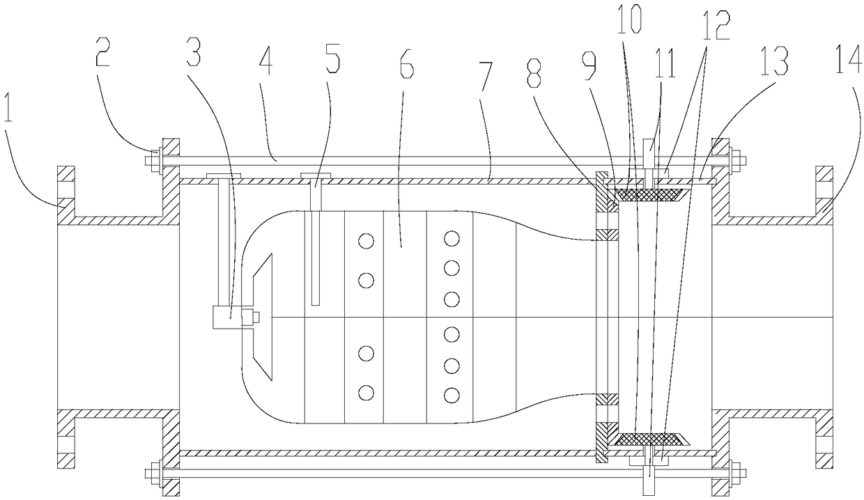
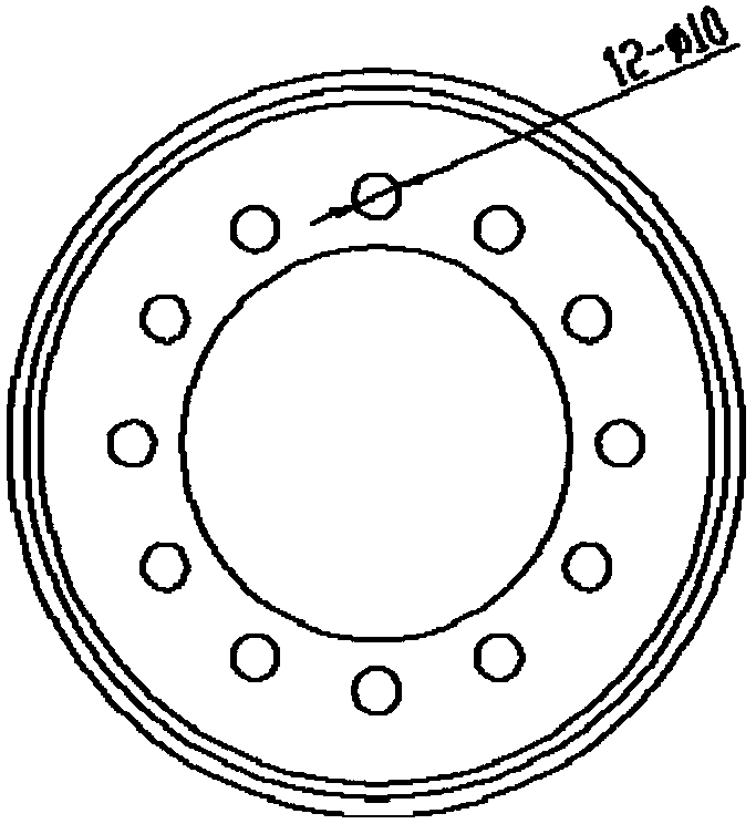
[0022] A turbocharger test bench combustor with adjustable outlet temperature, such as Figures 1 to 5 As shown, it includes front flange 1, bolt 2, nozzle 3, tie rod 4, ignition rod 5, flame cylinder 6, casing cylinder 7, flame cylinder flange 8, temperature adjustment mechanism, mixing section outer cylinder 13 and rear flange 14,
[0023] The afterbody of described flame tube 6 is fixedly installed flame tube flange 8, and described casing tube 7 is socketed on the outside of flame tube 6, and one end is connected with flame tube flange 8, and the other end is in contact with front flange 1; One end of the section outer cylinder 13 is connected to the other side of the flame cylinde...
PUM
 Abstract
Description
Claims
Application Information