Winding tube type heat exchanger with circular tube flow guider and inner lining barrel device

A winding tube type, lined tube technology, applied in the direction of heat exchanger type, heat exchanger shell, indirect heat exchanger, etc., can solve the problems of improving, affecting heat exchange efficiency, large flow dead zone, etc., to expand the medium flow area, improve heat exchange efficiency, and reduce the effect of medium flow dead zone

Inactive Publication Date: 2018-06-29
NANJING UNIV OF TECH
View PDF8 Cites 6 Cited by
  • Summary
  • Abstract
  • Description
  • Claims
  • Application Information

AI Technical Summary

Problems solved by technology

[0004] The purpose of the present invention is to solve the problem that the flow dead zone of the existing coiled tube heat exchanger is large and the flow short circuit area is generated in the coil area, which affects the improvement of heat exchange efficiency. Wound tube heat exchanger with tube deflector and inner liner device

Method used


Image

  • Winding tube type heat exchanger with circular tube flow guider and inner lining barrel device
  • Winding tube type heat exchanger with circular tube flow guider and inner lining barrel device
  • Winding tube type heat exchanger with circular tube flow guider and inner lining barrel device

Examples


Embodiment 1

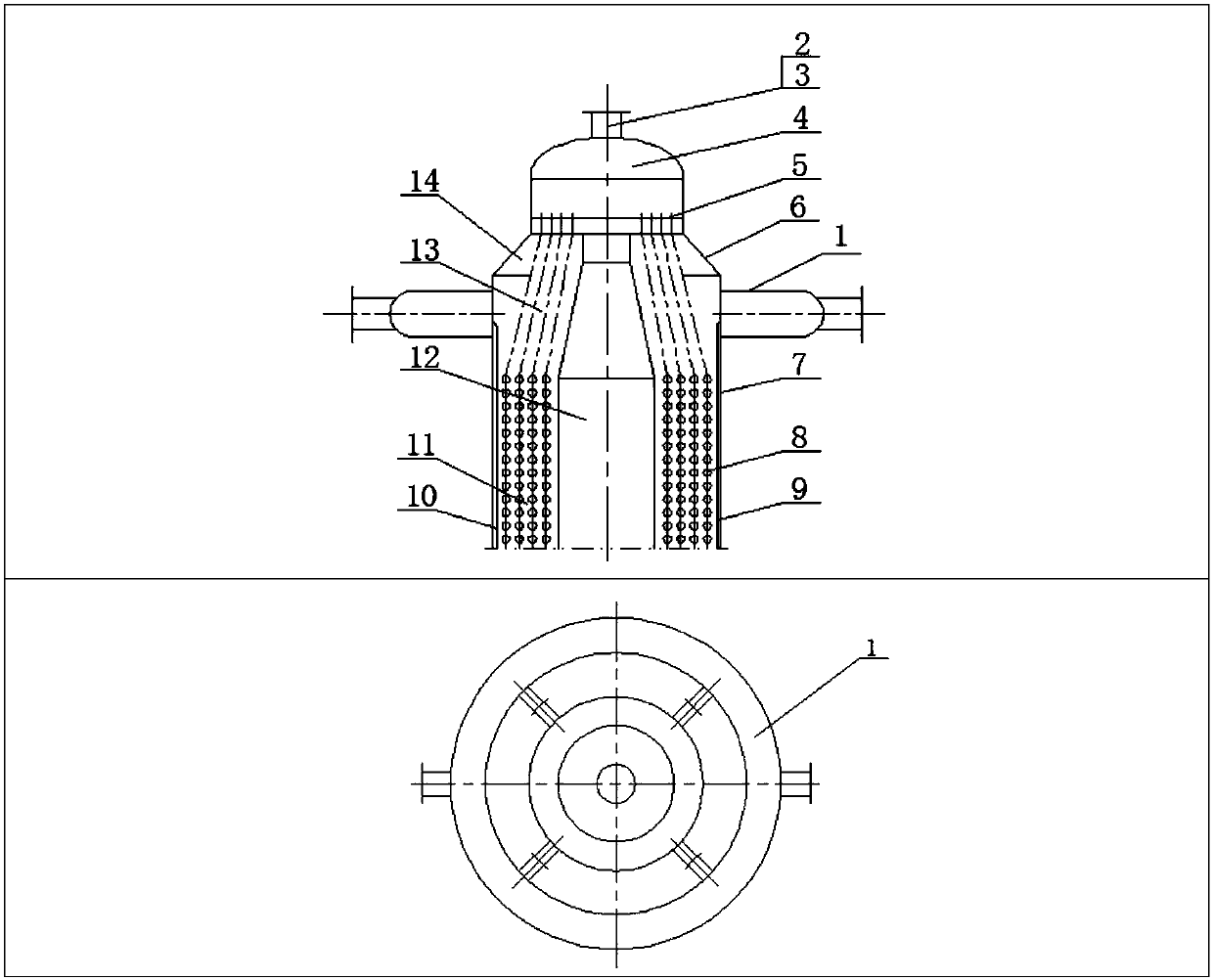
[0038] Such as figure 2 , image 3 a), Figure 4-7 shown.

[0039]A coiled tube heat exchanger with a ring tube deflector and an inner liner device, which includes a tube box 4, a tube sheet 5 and a shell-side cylinder 7, the tube box 4 is connected with a head, and the tube sheet 5- One side is connected to the tube box 4, and the other side is connected to the shell-side conical tube section 6. A core tube 12 that runs through the entire heat exchanger is installed in the shell-side tube 7, and heat exchange tubes 8 are installed around the core tube 12. And in the inner and lower part of the process cylinder 7, a coiled tube heat exchange zone 11 is formed, and a straight tube transition zone 13 is formed between the tube sheet 5 and the tube coiled zone 11, which is characterized in that the shell-side cylinder corresponding to the straight tube transition zone 13 The outer side of the body 7 is equipped with a circular pipe deflector 1, which communicates with the rea...

Embodiment 2

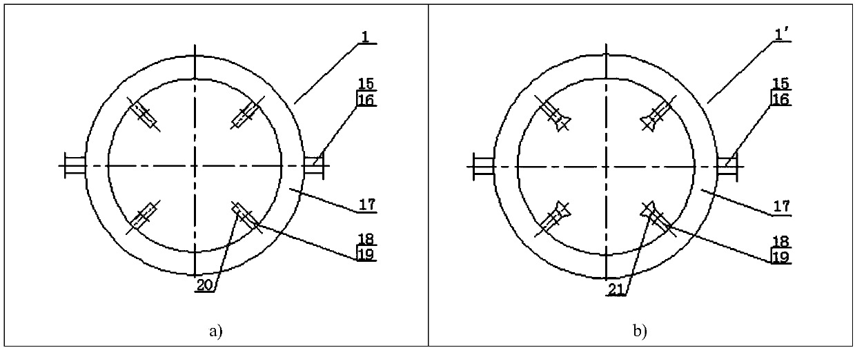
[0044] Such as image 3 b), Figure 4 , Figure 8-11 shown.

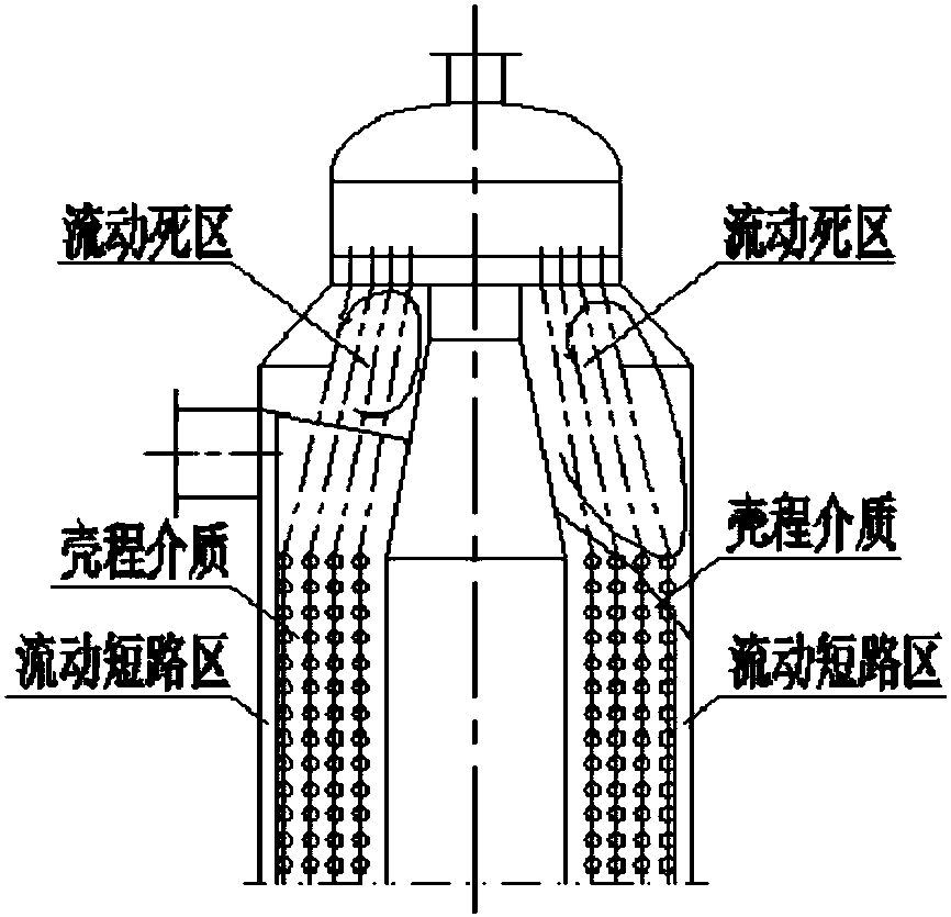
[0045] Such as Figure 8 As shown, the difference between the present embodiment and the first embodiment is that a trumpet-type annular tube deflector 1' and an inner liner 10 are installed in the heat exchanger, and the tube-side connecting pipe 2 and the pipe-side connecting pipe are arranged on the head of the pipe box 4 Flange 3, one side of tube sheet 5 is connected to tube box 4, and the other side is connected to shell-side conical barrel section 6. There is a straight tube transition area 13 between tube sheet 5 and tube winding area 11, and the straight tube transition area 13 and There is a transitional cavity area 14 between the shell-side conical cylinder section 6 and the shell-side cylinder 7 , and a flow stagnation zone 9 exists between the inner liner 10 and the shell-side cylinder 7 .

[0046] Such as image 3 As shown in b), the horn tube type annular tube deflector 1' comprises an inlet flan...

Embodiment 3

[0054] The difference between this embodiment and Embodiments 1 and 2 is that the entire heat exchanger only adopts the annular pipe deflector 1 to reduce the flow dead zone, and does not install the inner liner at the lower part of the shell cylinder, which can also significantly improve the heat transfer. Efficiency, but higher heat loss. This scheme can be used as appropriate according to the heat loss situation.


PUM


Abstract

The invention discloses a winding tube type heat exchanger with a circular tube flow guider and an inner lining barrel device. The winding tube type heat exchanger comprises a tube box (4), a tube plate (5) and a shell pass barrel body (7), and the winding tube type heat exchanger is characterized in that the annular tube flow guider (1) is mounted on the outer side of the shell pass barrel body(7) corresponding to a straight tube transitional area (13); on one hand, the annular tube flow guider (1) communicates with a reaction medium, and on the other hand, the annular tube flow guider (1)uniformly conveys the medium into the straight tube transitional area (13) through multiple channels; simultaneously/or, the inner lining barrel (10) is mounted in a barrel body, corresponding to a winding tube heat exchange area (11), of the inner part of the shell pass barrel body (7); the upper end of the inner lining barrel (10) is hermetically connected with an inner wall of the shell pass barrel body (7); and a channel into which the medium enters is reserved between the lower end of the inner lining barrel (10) and the inner wall of the shell pass barrel body (7). According to the winding tube type heat exchanger disclosed by the invention, a flowing dead area of an entrance part of a shell pass medium is reduced, a flowing area of the shell pass medium is widened, a flowing gap isreduced, flowing short-circuit of the shell pass medium is effectively improved, an effective utilization ratio of the heat exchange area of the winding tube type heat exchanger is increased, and theoverall heat exchange efficiency of the heat exchanger is also obviously improved.

Description

technical field [0001] The present invention relates to a heat pipe heat exchanger, in particular to a coiled tube heat exchanger, in particular to a coiled tube heat exchanger with a ring tube deflector and an inner lining tube device with few flow dead zones. heater. Background technique [0002] The shell side medium inlet of the wound tube heat exchanger is generally located on the transition section between the tube sheet and the heat exchange tube winding area. After the shell side medium flows in, it will be hindered by the core tube. When the shell side medium is fed by a single channel , the flow is not uniform in the transition cavity area near the inlet of the shell medium and the transition area of ​​the straight pipe, and there is a large flow dead zone (such as figure 1 As shown), part of the heat exchange tubes in the transition zone of the straight tubes did not participate in the heat exchange, which affected the heat exchange effect. [0003] When the coi...

Claims


Application Information

Patent Timeline
Patent Type & Authority Applications(China)
IPC IPC(8): F28D7/00F28F9/02F28F9/00
CPCF28D7/0041F28F9/00F28F9/026
Inventor 李庆生陈邦强贺小华李政辉
Owner NANJING UNIV OF TECH
Why Eureka
Try Eureka