
Laser detection type combustion chamber temperature detection device

A technology of laser detection and laser measurement, which is applied in measuring devices, optical radiation measurement, sensing radiation from gas/flame, etc., and can solve problems such as failure to receive laser signals, angle deviation of laser signals, damage to sensitive spectral components, etc.

Pending Publication Date: 2018-06-29
NANJING SCIYON AUTOMATION GRP
View PDF3 Cites 3 Cited by
  • Summary
  • Abstract
  • Description
  • Claims
  • Application Information

AI Technical Summary

Problems solved by technology

[0004] 1. Due to the coking of the observation port, the laser signal cannot be received;
[0005] 2. Dust accumulation makes it impossible to receive laser signals;
[0006] 3. Long-term high-temperature environment work causes damage to electronic, optical or other sensitive spectral components;
[0007] 4. The thermal expansion of the boiler itself causes slight changes in the position of the equipment, and the angle deviation of the received laser signal
At present, there is no suitable device that can solve the above problems. Therefore, we urgently need to develop a device to solve the above-mentioned difficulties and problems encountered in the implementation of laser TDLAS technology for detection of coal-fired boilers in power plants.

Method used


Image

  • Laser detection type combustion chamber temperature detection device
  • Laser detection type combustion chamber temperature detection device
  • Laser detection type combustion chamber temperature detection device

Examples


Embodiment Construction

[0035] The laser temperature detection device for the furnace of a power plant will be described in detail below in conjunction with the accompanying drawings.

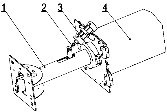
[0036] Such as figure 1 As shown in the present invention, a furnace temperature detection device using laser detection includes a bracket 1 , a decoking device 2 , a soot blowing cooling device 3 and a laser detection device 4 . The decoking device 2 , the soot blowing cooling device 3 and the laser detection device 4 are all installed on the bracket 1 .

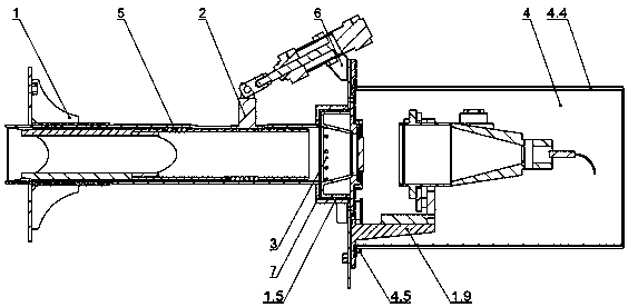
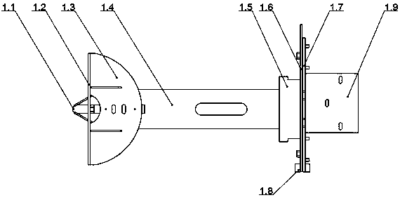
[0037] Such as figure 2 and image 3 As shown, the bracket 1 includes a fixed plate 1.2, a support plate 1.3, a seamless steel pipe 1.4, a cooling chamber 1.5, a mounting plate 1.6, a mounting plate 1.7, a hinge 1.8, and a mounting base 1.9; Through hole, the front end of the seamless steel pipe 1.4 is cut into a V-shaped structure, with baffles welded on both sides, and an approximately rectangular viewing port is formed at the V-shaped apex, and the V-shaped ...


PUM


Abstract

The invention discloses a laser detection type combustion chamber temperature detection device, which comprises a supporting frame, a decoking device, a soot blowing and cooling device and a laser detection device. The supporting frame comprises a seamless steel pipe; one end of the decoking device is arranged in the seamless steel pipe and capable of axially and freely sliding; the decoking device is provided with a forked head portion which extends out of the front end of the supporting frame during decoking; the soot blowing and cooling device and the laser detection device are sequentiallyfixed to the rear end of the supporting frame; one end of the soot blowing and cooling device is communicated with the seamless steel pipe while the other end is sealed through a windproof filter, and the soot blowing and cooling device is provided with an air inlet. During laser detection, laser emitted by the laser detection device sequentially penetrates the soot blowing and cooling device andthe supporting frame to enter a to-be-detected combustion chamber or sequentially penetrates the supporting frame and the soot blowing and cooling device to be received by the laser detection device.By arrangement of the supporting frame, the decoking device and the soot blowing and cooling device, problems of high temperature, high dust and proneness to coking of a viewport in implementation ofa TDLAS (tunable diode laser absorption spectroscopy) system is effectively solved.

Description

technical field [0001] The invention relates to a furnace temperature detection device using laser detection, in particular to a device for detecting the temperature of the furnace by analyzing the laser light passing through the furnace of a power plant. Background technique [0002] The boiler CT system based on laser TDLAS technology uses advanced laser measurement technology and uses the infrared absorption spectrum characteristics of gas molecules to collect and record infrared laser spectral absorption data at characteristic wavelengths, accurately obtain combustion parameters in the power plant furnace, and monitor the power plant furnace in real time Distribution parameter of outlet temperature field. [0003] Coal-fired power generation equipment in power plants generally has a combustion chamber with a diameter of 10-20 meters. This type of equipment burns pulverized coal, which makes the observation port high in dust, high temperature, and easy to coke. In such a...

Claims


Application Information

Patent Timeline
Patent Type & Authority Applications(China)
IPC IPC(8): G01J5/00
CPCG01J5/0014
Inventor 赵文庆施长庆曹浦龙芮梧赖小明
Owner NANJING SCIYON AUTOMATION GRP
Learn More