
Mask plate, display substrate and display device

A mask and substrate technology, which is used in optics, instruments, and photoengraving processes of pattern surfaces to achieve the effect of increasing the number of pixels, improving resolution, and high resolution.

Inactive Publication Date: 2018-06-29
BOE TECH GRP CO LTD +1
View PDF6 Cites 0 Cited by
  • Summary
  • Abstract
  • Description
  • Claims
  • Application Information

AI Technical Summary

Problems solved by technology

[0004] The inventor of the present application found in the process of implementing the application that the resolution of the TFT-LCD can only be improved within a limited range when using the PSM in the prior art for exposure. When the resolution of the TFT-LCD is required to be higher, This PSM is no longer applicable

Method used


Image

  • Mask plate, display substrate and display device
  • Mask plate, display substrate and display device
  • Mask plate, display substrate and display device

Examples


Embodiment Construction

[0048] In order to improve the resolution of the display device, thereby improving the display quality of the display device, embodiments of the present invention provide a mask plate, a display substrate and a display device. In order to make the purpose, technical solution and advantages of the present invention clearer, the following examples are given to further describe the present invention in detail.

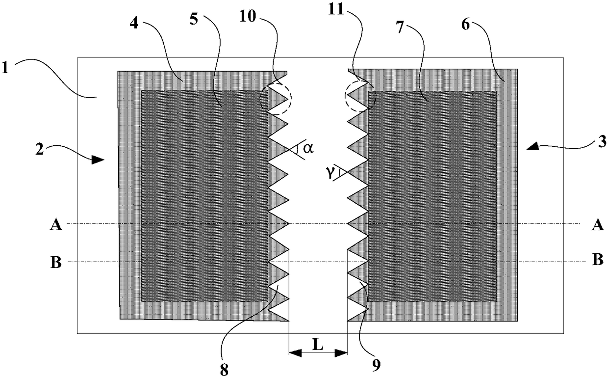
[0049] Such as Figure 2 to Figure 10 As shown, the embodiment of the present invention provides a mask plate, including a substrate 1, and a first exposure structure 2 and a second exposure structure 3 located on one side of the substrate 1 and oppositely arranged, wherein:

[0050] The first exposure structure 2 includes a first light-transmitting film layer 4 and a first light-shielding film layer 5 , the orthographic projection of the first light-shielding film layer 5 on the substrate 1 falls into the orthographic projection of the first light-transmitting film layer...


PUM


Abstract

The invention relates to the technical field of display device manufacturing, discloses a mask plate, a display substrate, and a display device, and aims to improve the resolution and the display quality of the display device. The mask plate comprises a substrate, a first exposure structure, and a second exposure structure, wherein the first exposure structure and the second exposure structure areoppositely arranged on one side of the substrate. The first exposure structure comprises a first transparent film layer and a first opaque film layer. The orthographic projection of the first opaquefilm layer falls into the orthographic projection of the first transparent film layer. The second exposure structure comprises a second transparent film layer and a second opaque film layer. The orthographic projection of the second opaque film layer falls into the orthographic projection of the second transparent film layer. The side, which is close to the second exposure structure, of the firstexposure structure has a first zigzag structure. The side, which is close to the first exposure structure, of the second exposure structure has a second zigzag structure.

Description

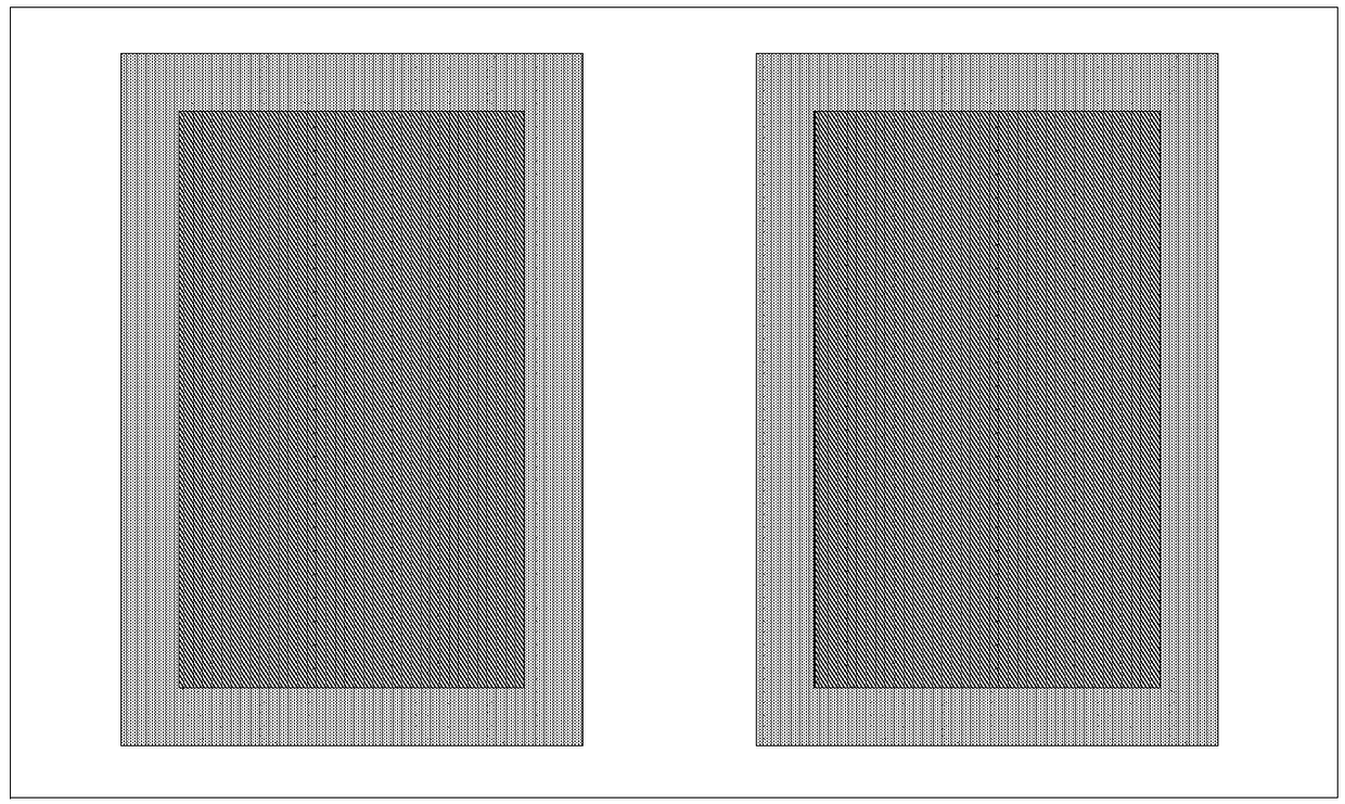
technical field [0001] The present invention relates to the technical field of display device manufacturing, in particular to a mask plate, a display substrate and a display device. Background technique [0002] Among flat panel display devices, Thin Film Transistor Liquid Crystal Display (TFT-LCD) has the characteristics of small size, low power consumption, relatively low manufacturing cost and no radiation, and occupies a dominant position in the current flat panel display market. status. [0003] In the preparation process of TFT-LCD, such as figure 1 The shown phase shift mask (Phase Shift Mask, referred to as PSM) exposes the TFT, so that the distance between each metal line is reduced, thereby increasing the number of pixel units, and then obtaining a TFT-LCD with a higher resolution. [0004] The inventor of the present application found in the process of implementing the application that the resolution of the TFT-LCD can only be improved within a limited range whe...

Claims


Application Information

Patent Timeline
Patent Type & Authority Applications(China)
IPC IPC(8): G03F1/26
CPCG03F1/26G02F1/1303G02F1/1362G03F1/38G03F1/58G03F1/44
Inventor 张小祥郭会斌宋勇志刘明悬徐文清李小龙吴祖谋
Owner BOE TECH GRP CO LTD
Learn More