A Forced Stability Control Method for Torsional Vibration of Permanent Magnet Direct Drive Transmission Shafting

A transmission shaft and direct drive technology, applied in the direction of adaptive control, general control system, control/adjustment system, etc., can solve problems such as self-excited torsional vibration, torque increase, catastrophe, etc., to suppress torsional vibration and avoid Effects of torsional vibration and improved robustness

Active Publication Date: 2020-08-07
CHINA UNIV OF MINING & TECH
View PDF13 Cites 0 Cited by
  • Summary
  • Abstract
  • Description
  • Claims
  • Application Information

AI Technical Summary

Problems solved by technology

[0004] The existing control methods for the torsional vibration of the transmission shaft system are mostly aimed at the transmission mode of "asynchronous motor + reducer", and rarely consider the influence of the output characteristics of the drive end on the torsional vibration of the system transmission shaft system.
However, for the wind turbine pitch system directly driven by the low-speed high-torque permanent magnet motor, since the low-speed high-torque permanent magnet motor is used to directly drive the blades of the wind turbine, the torque transmitted by the drive shaft of the system will be significantly larger, and torsional vibration Energy is exchanged and stored between the electromagnetic energy at the motor end and the kinetic energy of the system drive shaft. Under certain conditions, the electrical system and the mechanical system just form the basic system of self-excited vibration, and self-excited torsional vibration is bound to occur, which in turn leads to catastrophic failure. as a result of

Method used


Image

  • A Forced Stability Control Method for Torsional Vibration of Permanent Magnet Direct Drive Transmission Shafting
  • A Forced Stability Control Method for Torsional Vibration of Permanent Magnet Direct Drive Transmission Shafting
  • A Forced Stability Control Method for Torsional Vibration of Permanent Magnet Direct Drive Transmission Shafting

Examples


Embodiment Construction

[0024] The present invention will be further described below in conjunction with accompanying drawing.

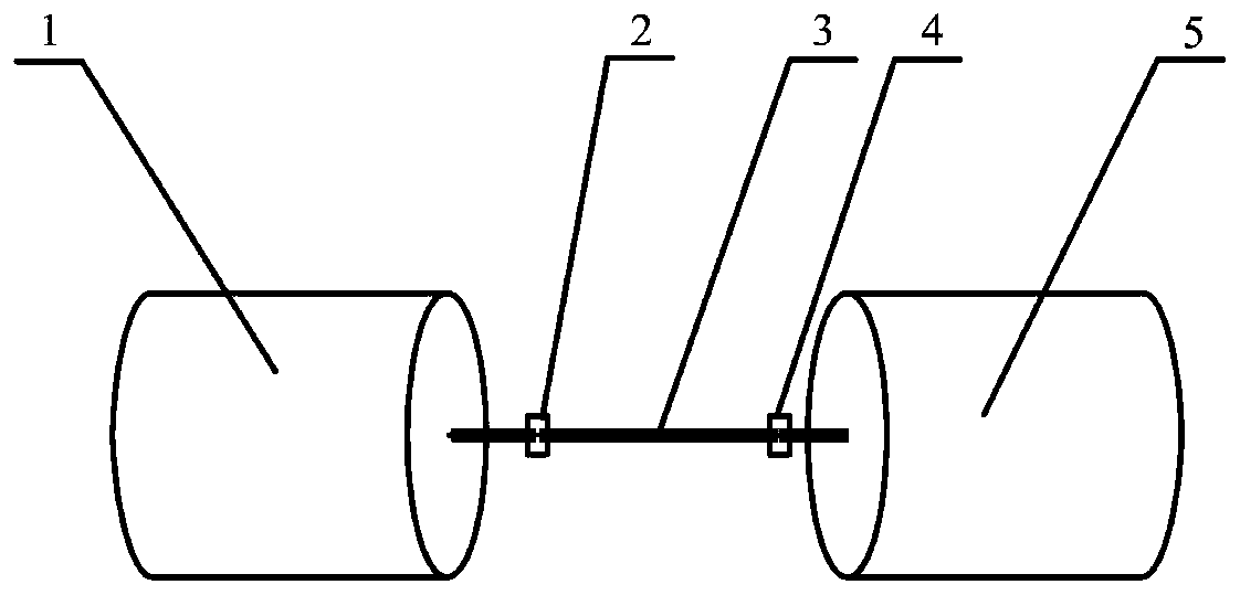
[0025] Such as figure 1 As shown, a wind power generator variable pitch system transmission system using the method of the present invention, the output shaft of the low-speed high-torque permanent magnet motor 1 is directly connected with the wind power generator variable pitch transmission shaft system 3 through the coupling I2, and the wind power generator becomes The pitch drive shaft system 3 is connected to the blade roller 5 through the coupling II4, and the direct drive of the blade roller 5 by the low-speed high-torque permanent magnet motor 1 is realized through the above connection method. By rationally designing the torsional vibration forced stability controller of the wind turbine pitch system directly driven by the low-speed high-torque permanent magnet motor, the safe and reliable application of the low-speed high-torque permanent magnet motor 1 in the wind ...


PUM


Abstract

The invention discloses a forced stable control method for torsional vibration of a permanent magnet direct-drive driving shaft system. The method comprises the following specific steps: S1, determining an electromechanical coupling dynamic model of a system driving shaft system under the direct drive of a low-speed large-torque permanent magnet motor 1; S2, constructing a system full-state feedback regulator; S3, constructing a system input delay shaper; S4, integrating the system full-state feedback regulator and the system input delay shaper to construct a system torsional vibration forcedstable controller; S5, adjusting the control parameters of the system torsional vibration forced stable controller according to a numerical simulation result. After the steps, the design is finished.By adopting the forced stable control method, torsional vibration of the driving shaft system is avoided from the source, the robustness of the conventional closed loop controller can be enhanced remarkably, the aim of effectively suppressing the torsional vibration of the driving shaft system is fulfilled, and safe and reliable application of the low-speed large-torque permanent magnet motor in the field of direct drive is ensured.

Description

technical field [0001] The invention relates to the technical field of transmission shaft torsional vibration control, in particular to a permanent magnet direct drive type transmission shaft torsional vibration forced stability control method. Background technique [0002] With the increasing shortage of non-renewable energy and the increasingly prominent environmental problems caused by burning fossil energy, it is imperative to accelerate the development of new energy and take the road of sustainable development. In recent years, wind power generation has become a rapidly developing renewable energy power generation method in various countries due to its sufficient safety and cleanliness. [0003] The main purpose of wind turbine control is to increase high-quality electric energy with constant frequency and constant voltage to the grid on the basis of maximally capturing wind energy and reducing the impact on the grid. At this stage, on the one hand, the variable pitch ...

Claims


Application Information

Patent Timeline
Patent Type & Authority Patents(China)
IPC IPC(8): G05B13/04
CPCG05B13/042
Inventor 李威鞠锦勇王禹桥杨雪锋范孟豹许少毅路恩盛连超王承涛陈宇鸣姜耸陈家俊李敏王越
Owner CHINA UNIV OF MINING & TECH
Why Eureka
Try Eureka