Engine power transmission output structure

A power transmission and output structure technology, applied in the direction of machines/engines, mechanical equipment, etc., can solve problems such as difficulty in increasing power, reducing fuel consumption rate, and increasing stroke, so as to achieve power increase and manufacturing material saving , The effect of reducing the diameter of rotation

Active Publication Date: 2016-12-07
常熟东南高新技术创业服务有限公司
View PDF8 Cites 0 Cited by
  • Summary
  • Abstract
  • Description
  • Claims
  • Application Information

AI Technical Summary

Problems solved by technology

However, due to the four-stroke cycle mode, each cylinder only performs work once when it rotates two times, so it is difficult to increase its power greatly.
Due to the limitations of the stroke and bore ratio of the four-stroke engine, it is difficult to adopt a structure with a larger stroke, and it is difficult to increase the stroke, which also makes it difficult to reduce the fuel consumption rate
Regardless of the two-stroke engine or the four-stroke engine, there are disadvantages that are difficult to solve

Method used


Image

  • Engine power transmission output structure
  • Engine power transmission output structure
  • Engine power transmission output structure

Examples


Embodiment Construction

[0028] Embodiments of the present invention will be further described in detail below in conjunction with the accompanying drawings.

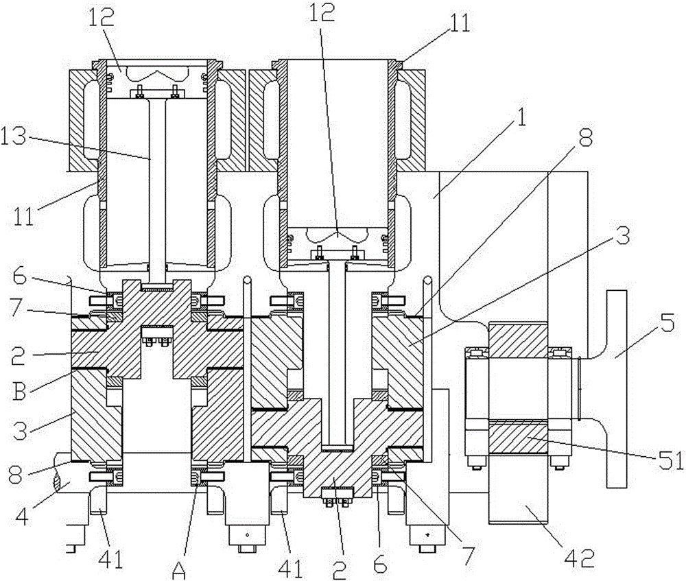
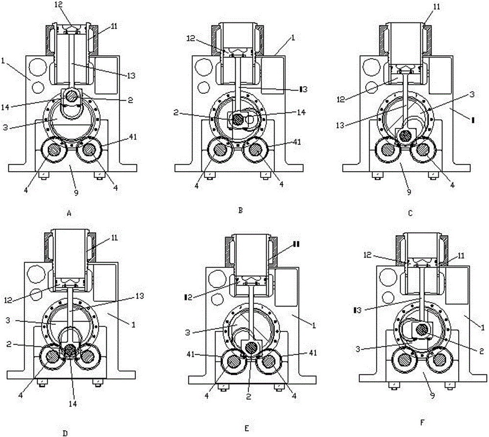
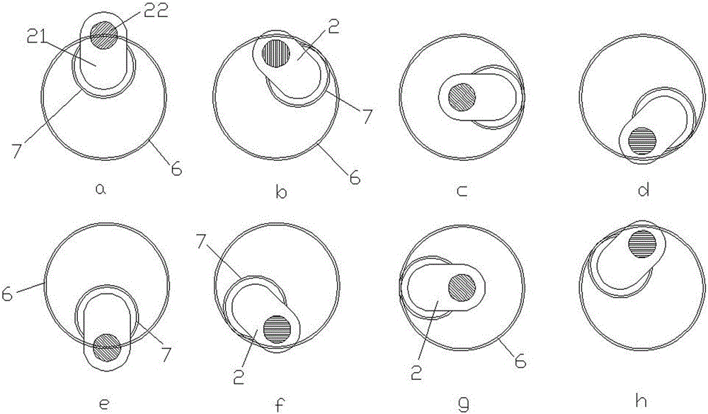
[0029] Figure 1 to Figure 10 It is a schematic diagram of the principle of the embodiment of the present invention.

[0030] The reference signs are: large gear bolt A, sliding bearing B, thrust ring C, rotation axis L, engine body 1, cylinder liner 11, piston 12, piston rod 13, connecting rod bush 14, rocker crank Pin 2, rocker crank 21, crank pin 22, output rocker gear 3, hub disc 31, transmission external gear 31a, rocker bearing hole 31b, balance weight 32, shaft section 33, torque common rail transmission shaft 4, output gear 41. Main drive gear 42, engine flywheel 5, slave drive gear 51, guide bull gear 6, inner ring teeth 61, guide pinion gear 7, outer ring teeth 71, main bearing bush 8, main bearing cap 9.

[0031] Figure 1 to Figure 10 It is the structure and transmission schematic diagram of the present invention, as shown in the...


PUM


Abstract

The invention discloses an engine power transmission output structure. The engine power transmission output structure comprises an engine body with a plurality of cylinders. Each cylinder in the engine body comprises a cylinder sleeve embedded in a corresponding cylinder sleeve hole of the engine body, a piston in the cylinder sleeve, and a piston rod connected with the piston, wherein a rocker crank pin is hinged to the piston rod, and the rocker crank pin is composed of rocker cranks on the two sides and a crank pin connecting the two rocker cranks. The engine body is internally provided with output rocker gears corresponding to the cylinders, and the output rocker gears are in power transmission connection with the rocker cranks of the rocker crank pins. The engine body is internally further provided with torque common rail transmission shafts, and the torque common rail transmission shafts are engaged with the output rocker gears to finally transmit and output power of all the cylinders to engine flywheels. The engine body is internally provided with large guiding gears corresponding to the cylinders. The rocker cranks of the rocker crank pins are sleeved with small guiding gears, and the small guiding gears do the circumferential movement in the large guiding wheels, so that the crank pins of the rocker crank pins do the vertical movement.

Description

technical field [0001] The invention relates to the technical field of engine design, in particular to the engine piston, connecting rod movement, crank pin movement trajectory, power transmission and output technology, in particular to an engine power transmission output structure. Background technique [0002] In the field of engines, two structures are basically used: two-stroke and four-stroke structures. Due to the adoption of power output mechanisms such as piston rods, crossheads and rocker arms, the two-stroke engine causes the engine to be too large, and the mass of the engine is several hundred tons or several thousand tons, resulting in a relatively high manufacturing cost of the two-stroke engine. Installation, use, and maintenance bring great difficulties, especially for special-purpose ships, such as large-tonnage official ships, surface ships, submarines, inland water ships, etc., due to the limitations of the ship's engine room, it is difficult to use such a ...

Claims


Application Information

Patent Timeline
Patent Type & Authority Applications(China)
IPC IPC(8): F02B61/06F02B75/32
CPCF02B61/06F02B75/32
Inventor 徐玉国
Owner 常熟东南高新技术创业服务有限公司
Why Eureka
Try Eureka