Permanent magnet stepless speed reducer

A continuously variable speed reducer technology, applied in the direction of electromechanical devices, control mechanical energy, electromechanical transmission devices, etc., can solve the problems of smooth leakage and oil leakage of the output shaft of the reducer, avoid shaft torsional vibration, high transmission efficiency, Easy to install effect

Active Publication Date: 2016-10-05
芜湖磁轮传动技术有限公司
View PDF8 Cites 0 Cited by
  • Summary
  • Abstract
  • Description
  • Claims
  • Application Information

AI Technical Summary

Problems solved by technology

With the increase of working time, the existing reducer generally has the problem of oil leakage, especially the problem of oil leakage along the output shaft of the reducer is very prominent

Method used


Image

  • Permanent magnet stepless speed reducer
  • Permanent magnet stepless speed reducer
  • Permanent magnet stepless speed reducer

Examples


Embodiment 1

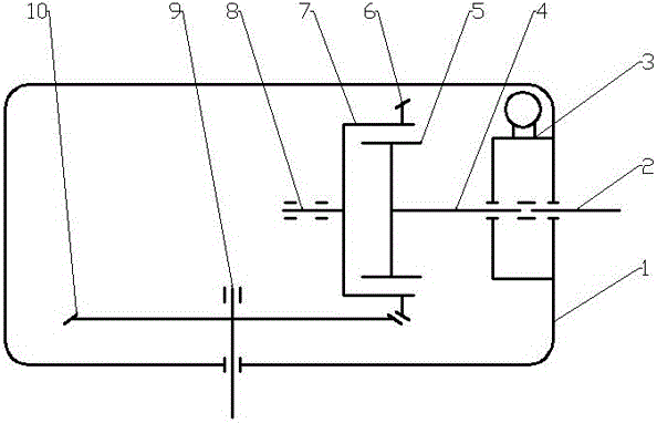
[0031] Such as figure 1 Shown: a permanent magnet continuously variable speed reducer, including a box body 1, a regulator 3 fixedly installed on the box body 1, and an input shaft 2, an adjustment shaft 4, a transmission shaft 8 and movably supported on the box body 1 The output shaft 9, the regulator 3 and the adjustment shaft 4 constitute the adjustment mechanism. The input shaft 2 is installed horizontally on the box body 1. The end of the input shaft 2 is sleeved with the adjustment shaft 4. The other end of the adjustment shaft 4 is connected to the cylindrical The permanent magnet rotor 5 is connected and the permanent magnet rotor 5, the adjustment shaft 4 and the input shaft 2 rotate synchronously. Specifically, the adjustment shaft 4 is sleeved on the input shaft 2 through a spline, so that the permanent magnet rotor 5 and the adjustment shaft 4 are in the position of the regulator. 3 slides left and right along the axial direction of the input shaft 2; the correspon...

Embodiment 2

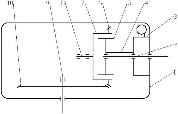
[0033] Such as figure 2Shown: a permanent magnet continuously variable speed reducer, including a box body 1, a regulator 3 fixedly installed on the box body 1, and an input shaft 2, a transmission shaft 8 and an output shaft 9 movably supported on the box body 1, The regulator 3 and the adjusting rod 41 form an adjusting mechanism, the input shaft 2 is installed horizontally on the box body 1, and the end of the input shaft 2 is provided with a permanent magnet rotor 5 which rotates together with it, and the permanent magnet rotor 5 is directly connected to one end of the adjusting rod 41. The other end of the adjustment rod 41 is connected to the regulator 3, and the permanent magnet rotor 5 is installed on the input shaft 2 through a spline, so that the permanent magnet rotor 5 and the input shaft 2 rotate together. Under the action, it slides left and right along the axial direction of the input shaft 2; the corresponding part of the permanent magnet rotor 5 is provided w...

Embodiment 3

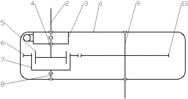
[0035] Such as image 3 Shown: a permanent magnet continuously variable speed reducer, including a box body 1, a regulator 3 fixedly installed on the box body 1, and an input shaft 2, an adjustment shaft 4, a transmission shaft 8 and movably supported on the box body 1 The output shaft 9, the regulator 3 and the adjustment shaft 4 constitute the adjustment mechanism, the input shaft 2 is vertically installed on the box body 1, and the lower end of the input shaft 2 is provided with the adjustment shaft 4 outside, and the lower end of the adjustment shaft 4 is connected with the cylindrical The permanent magnet rotor 5 is connected and the permanent magnet rotor 5, the adjustment shaft 4 and the input shaft 2 rotate synchronously. Specifically, the adjustment shaft 4 is sleeved on the input shaft 2 through a spline, so that the permanent magnet rotor 5 and the adjustment shaft 4 are in the position of the regulator. Under the action of 3, it slides up and down along the axial d...


PUM


Abstract

The invention discloses a permanent magnet continuously variable speed reducer, which comprises a box body (1), an input shaft (2), a transmission shaft (8) and an output shaft (9). The end of the input shaft (2) is provided with The permanent magnet rotor (5) rotates with it, and the corresponding part of the permanent magnet rotor (5) is provided with a conductor rotor (7) opposite to the permanent magnet rotor (5), and the conductor rotor (7) is fixed on the transmission shaft (8) and rotate together with the transmission shaft (8), and the outer peripheral surface of the conductor rotor (7) is provided with a driving gear (6), the driving gear (6) and the driven gear (10) installed on the output shaft (9) mesh with each other The permanent magnet rotor (5) makes the permanent magnet rotor (5) slide along the axial direction of the input shaft (2) through the adjustment mechanism to change the torque transmitted between the permanent magnet rotor (5) and the conductor rotor (7). The invention has the functions of stepless speed change and deceleration to increase torque, compact structure, convenient installation, high transmission efficiency and long service life.

Description

technical field [0001] The invention relates to the technical field of transmissions and reducers, in particular to a permanent magnet continuously variable speed reducer. Background technique [0002] A transmission is a device that can change the transmission ratio or speed of its output shaft and input shaft; the reducer plays a role in matching the speed and transmitting torque between the prime mover and the working machine or the actuator; the application of the transmission and the reducer in modern machinery is It is extremely extensive, but the transmission and the reducer are basically separate mechanical devices, and there are few speed reduction devices that integrate the two. When the existing mechanical gear transmission is used, the prime mover is rigidly connected to the working machine or the actuator, and a clutch needs to be used in the speed change process, and the mechanical gear transmission generally has a stepped speed regulation. With the increase o...

Claims


Application Information

Patent Timeline
Patent Type & Authority Patents(China)
IPC IPC(8): H02K51/00H02K7/116
Inventor 王向东林起崟黄忠念江晋民
Owner 芜湖磁轮传动技术有限公司
Why Eureka
Try Eureka